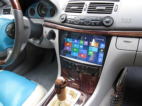
I present my CarPC project for a 2003 Mercedes-Benz E-Class W211, completed in 2014.
Why I Chose a PC
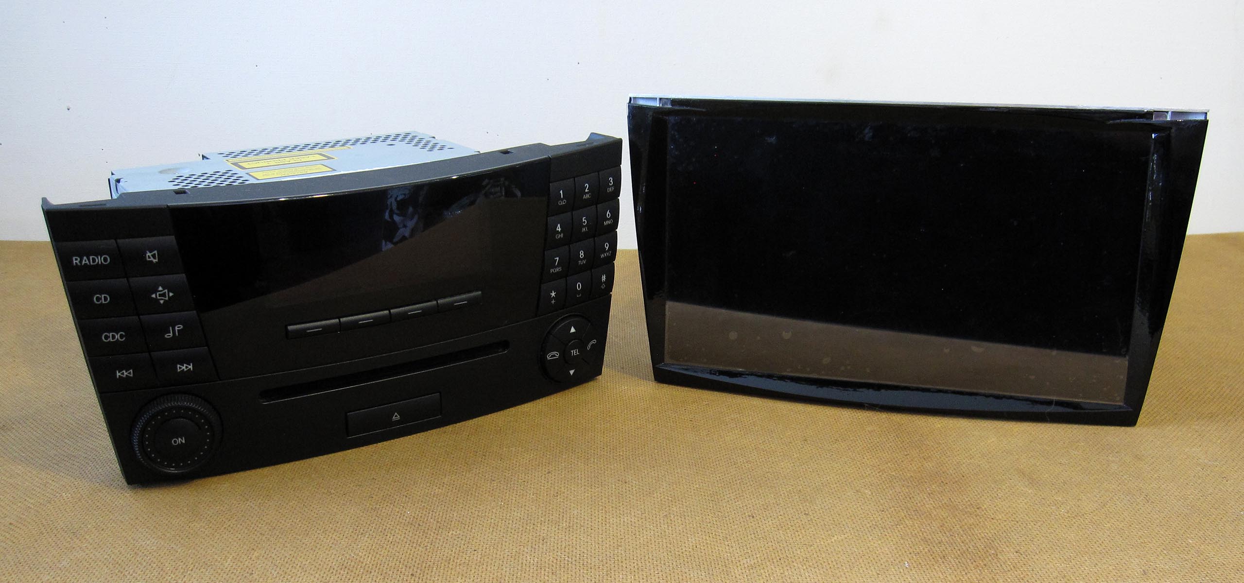
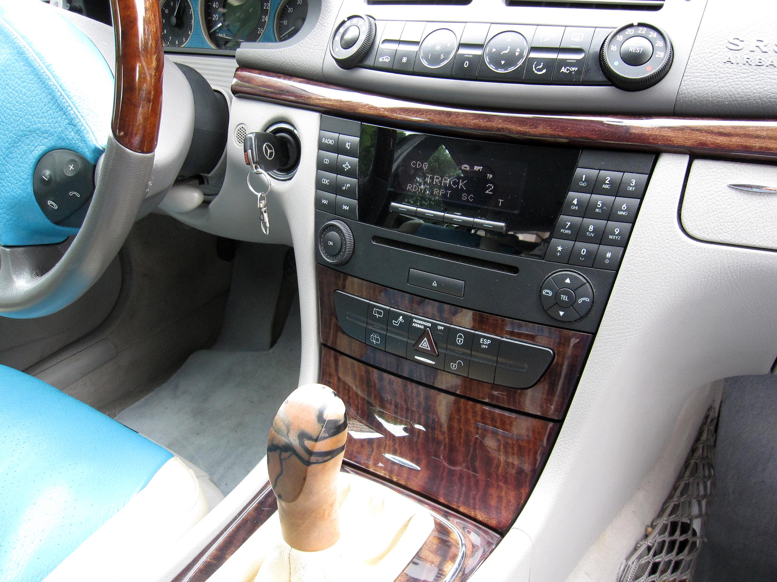
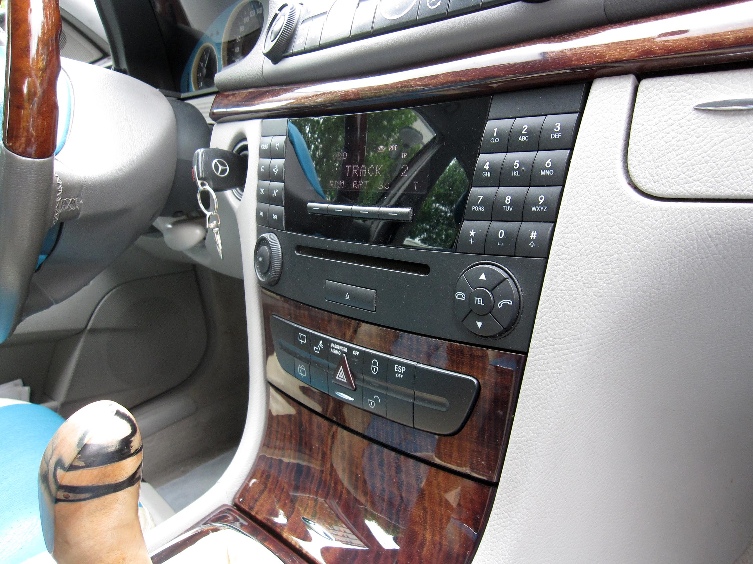
After weighing all the pros and cons of this project, I decided to remove the factory Audio 20 head unit, which does not even deliver high-quality sound, and install a CarPC in its place. It seemed to me that a CarPC, like any PC, offers far more advantages and possibilities than just a radio or navigation device.
First, I estimated that a 10.1-inch display could fit into the slot, which ruled out navigation units with 7- or 8-inch screens. Second, there is the limitation of navigation software: after a few years it becomes outdated, and updates are not always reliable. With a computer, navigation software can be installed according to personal preference in terms of design, functionality, and maps.
Another major advantage is the ability to play photos, videos, and music in various formats, as well as to use virtually any software and operating system.
Ultimately, my goal was to achieve improved Hi-Fi sound quality, ensuring that the entire car computer and amplifier would fit into the Audio 20 compartment without additional cables or control units, and that the entire modification would look professional.
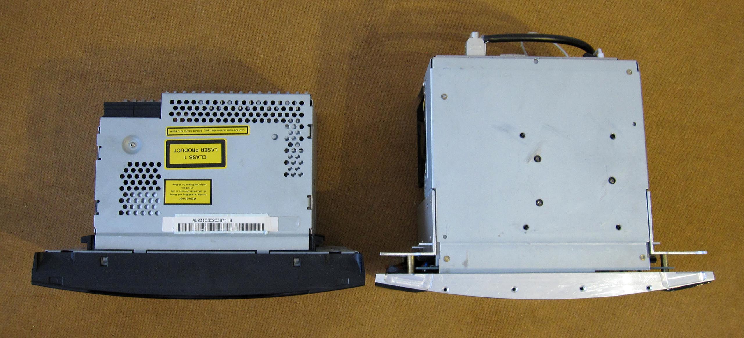
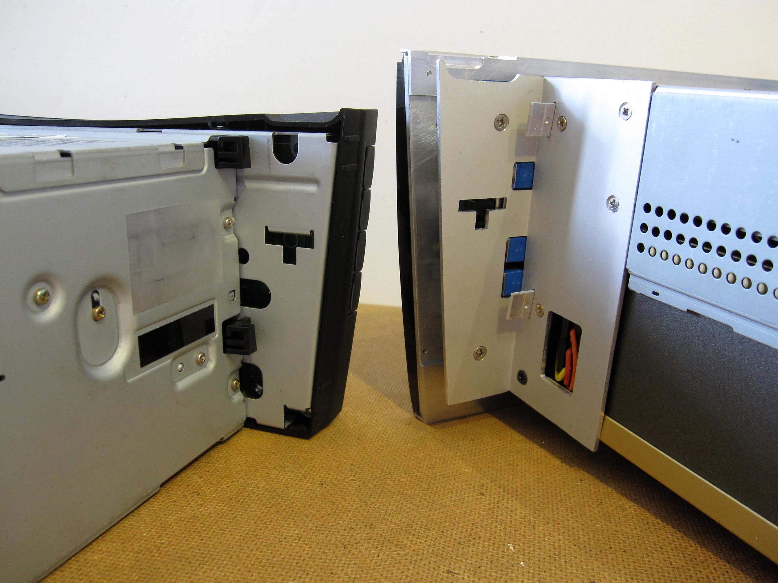
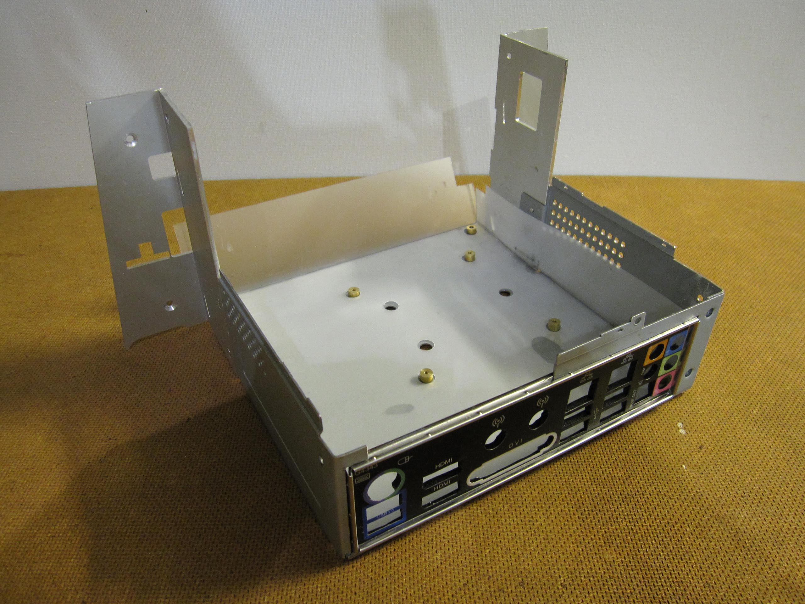
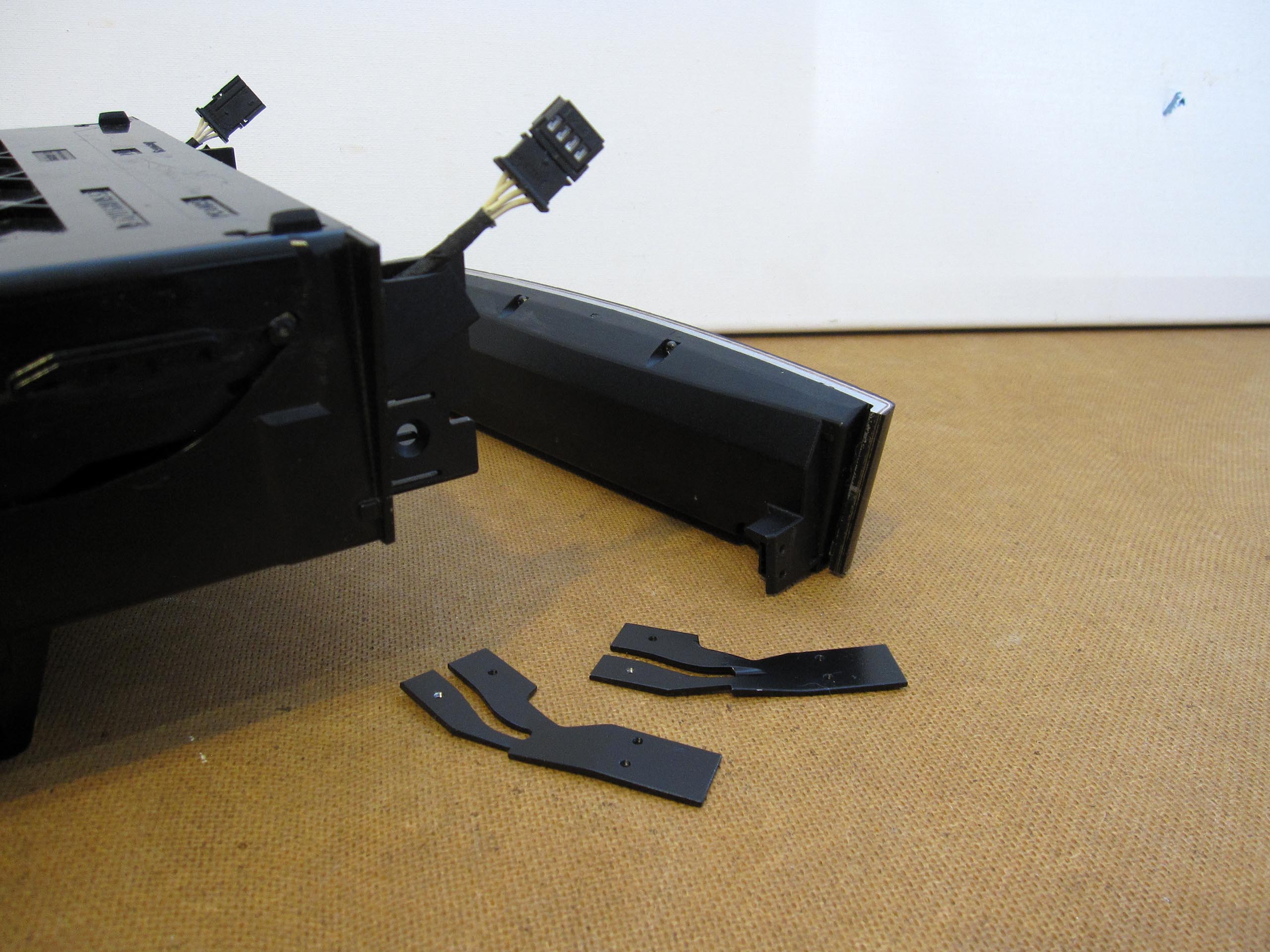
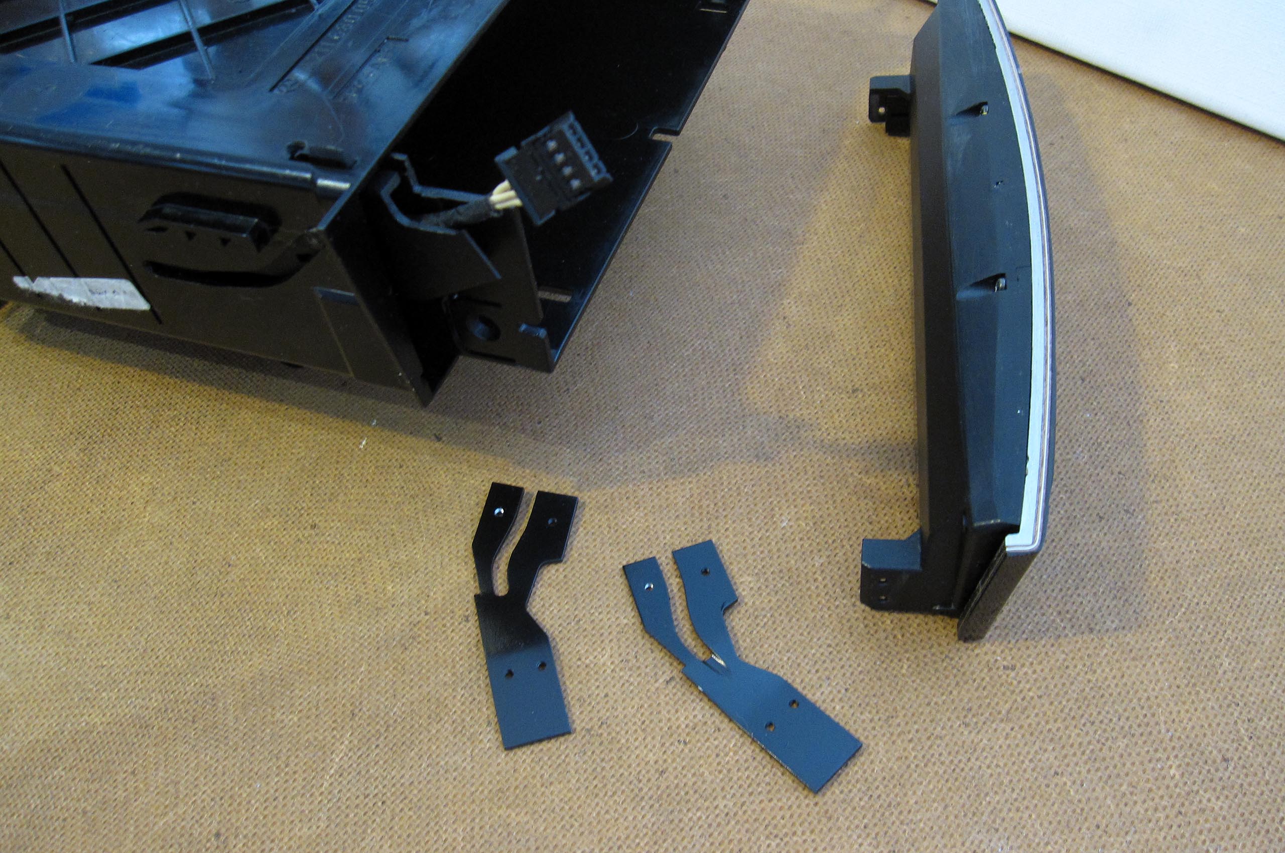
Looking ahead, it took three months from the start of assembly before I had the first opportunity to test my creation in action: the processor, motherboard, power supply, and amplifier installed in a case specially made to fit the car’s radio slot. For this purpose, connectors and wires had to be desoldered and resoldered, some components relocated, and others added. An important point: all of this was tested at home on a desk, not in the car.
During this time, I assembled and disassembled the housing together with the monitor and all components countless times to adjust its dimensions to the slot and to optimize the placement of the CarPC components.
Development and Assembly
In any case, I had to find a way to connect my creation to the vehicle’s CAN bus.
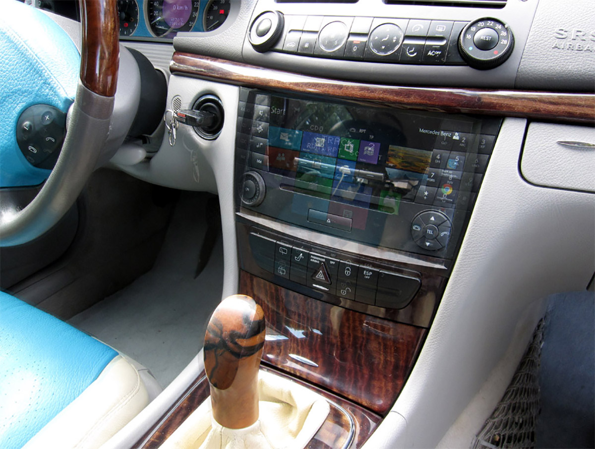
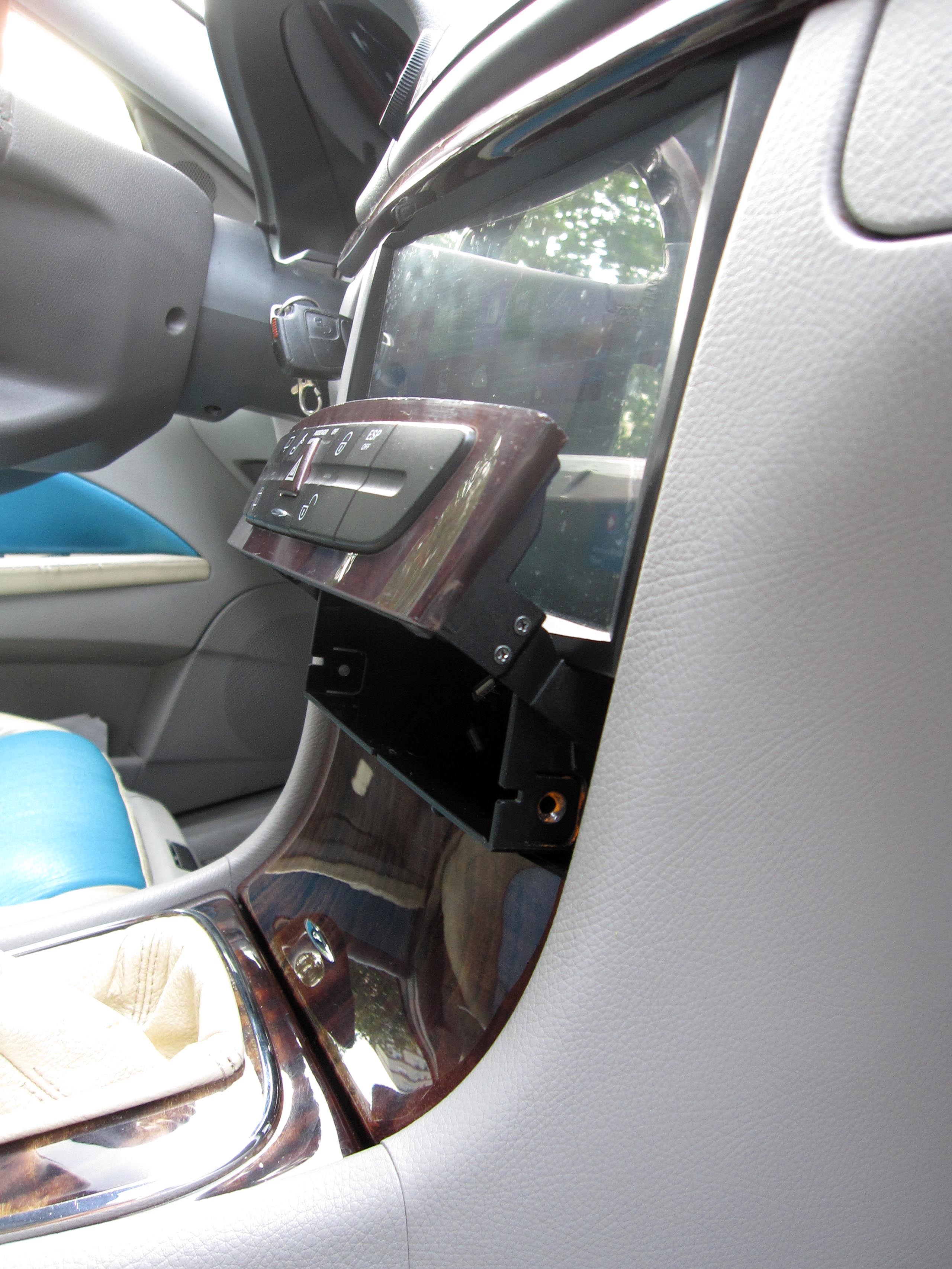
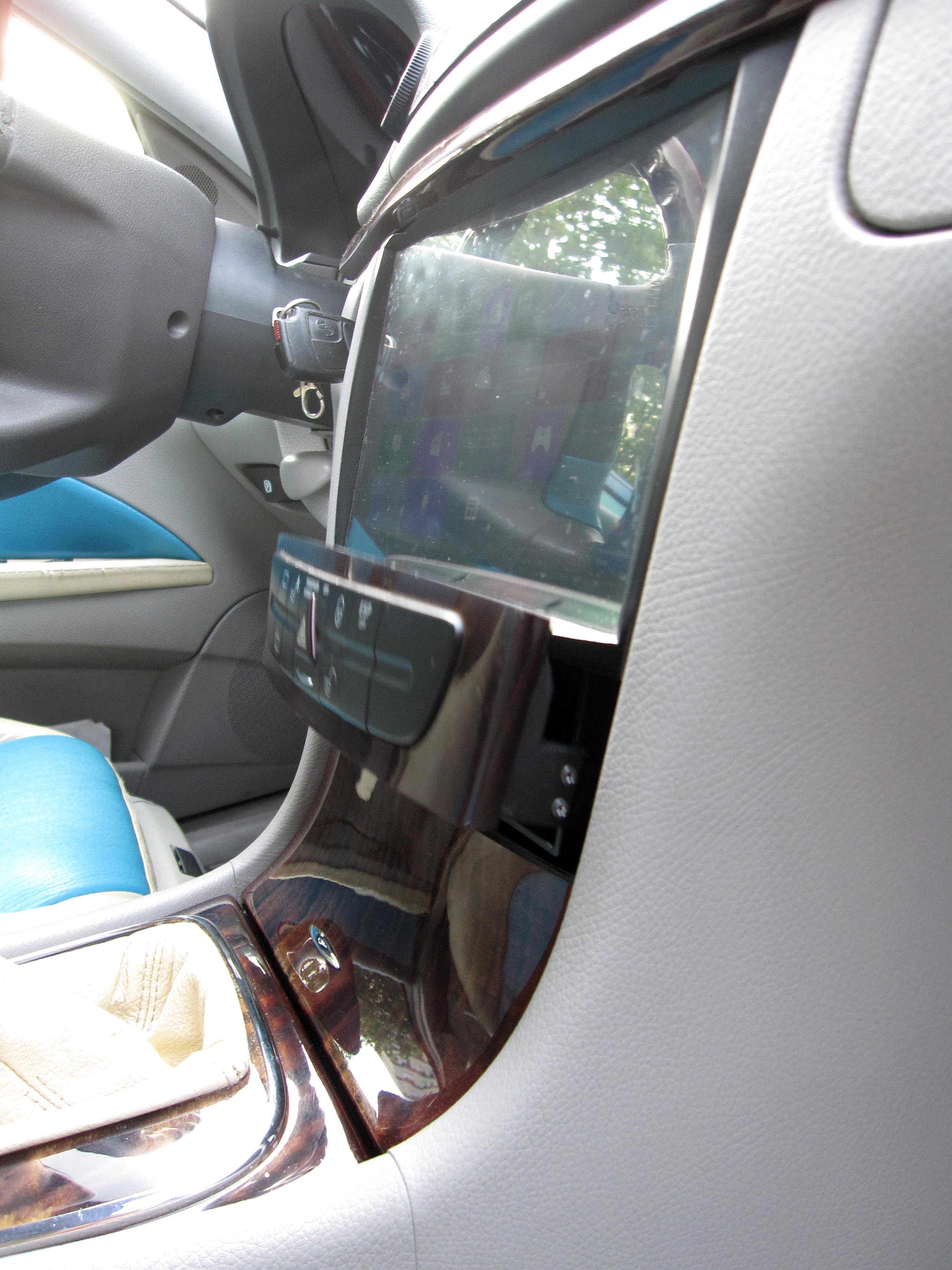
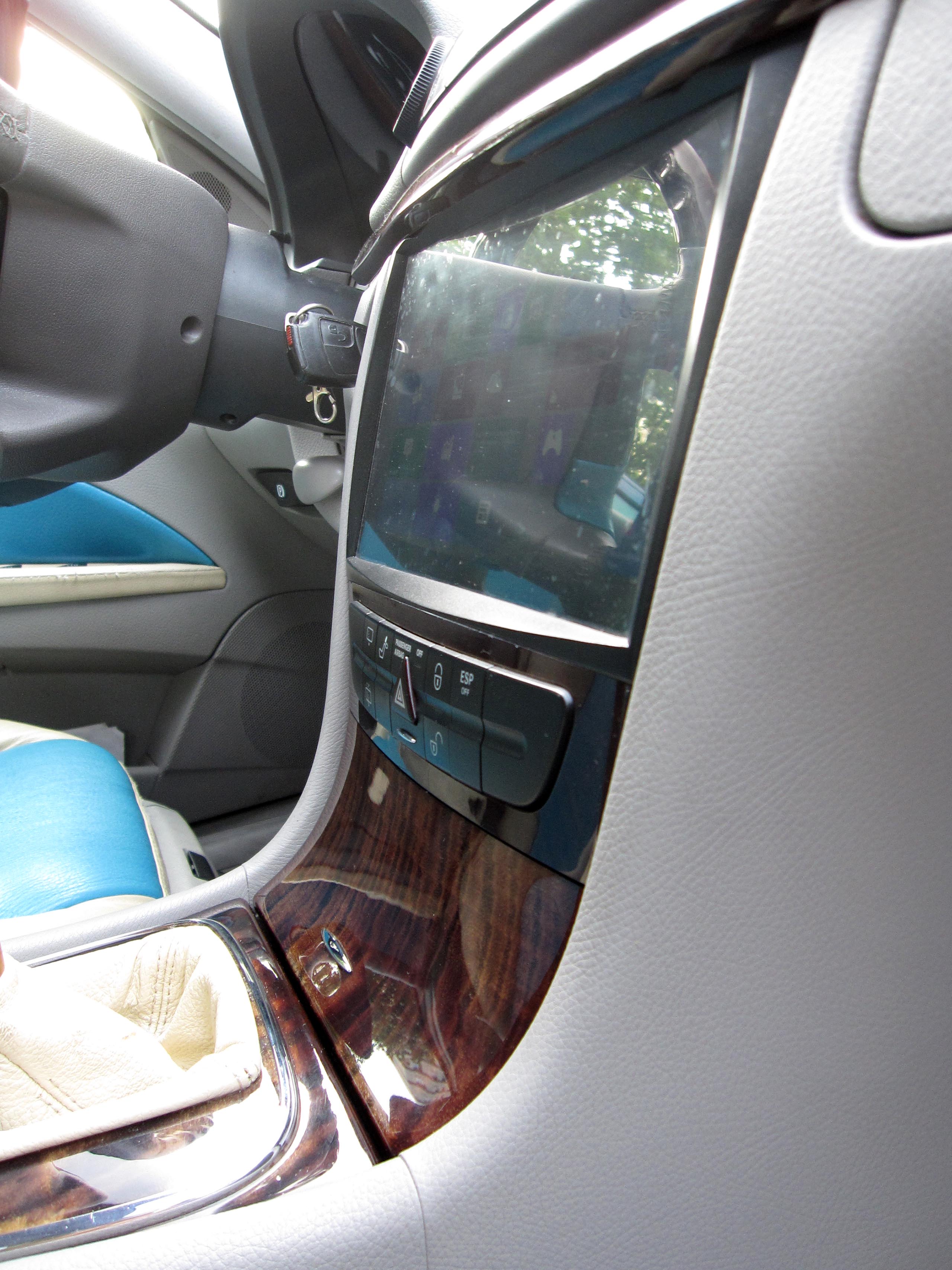
Photomontage: in the image, the outline of the monitor in its frame can be seen superimposed over the head unit.
Overall Analysis and Plan
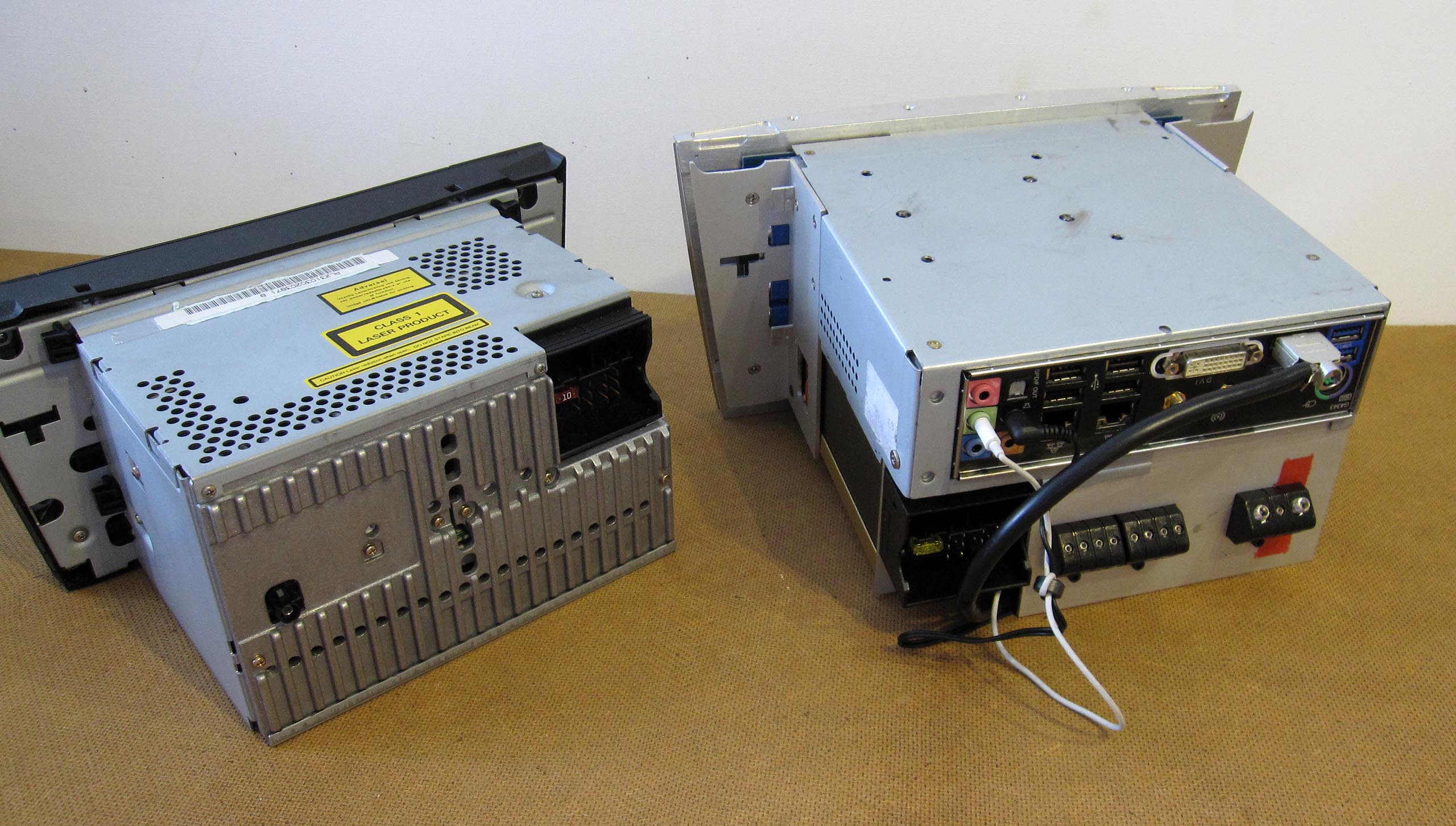
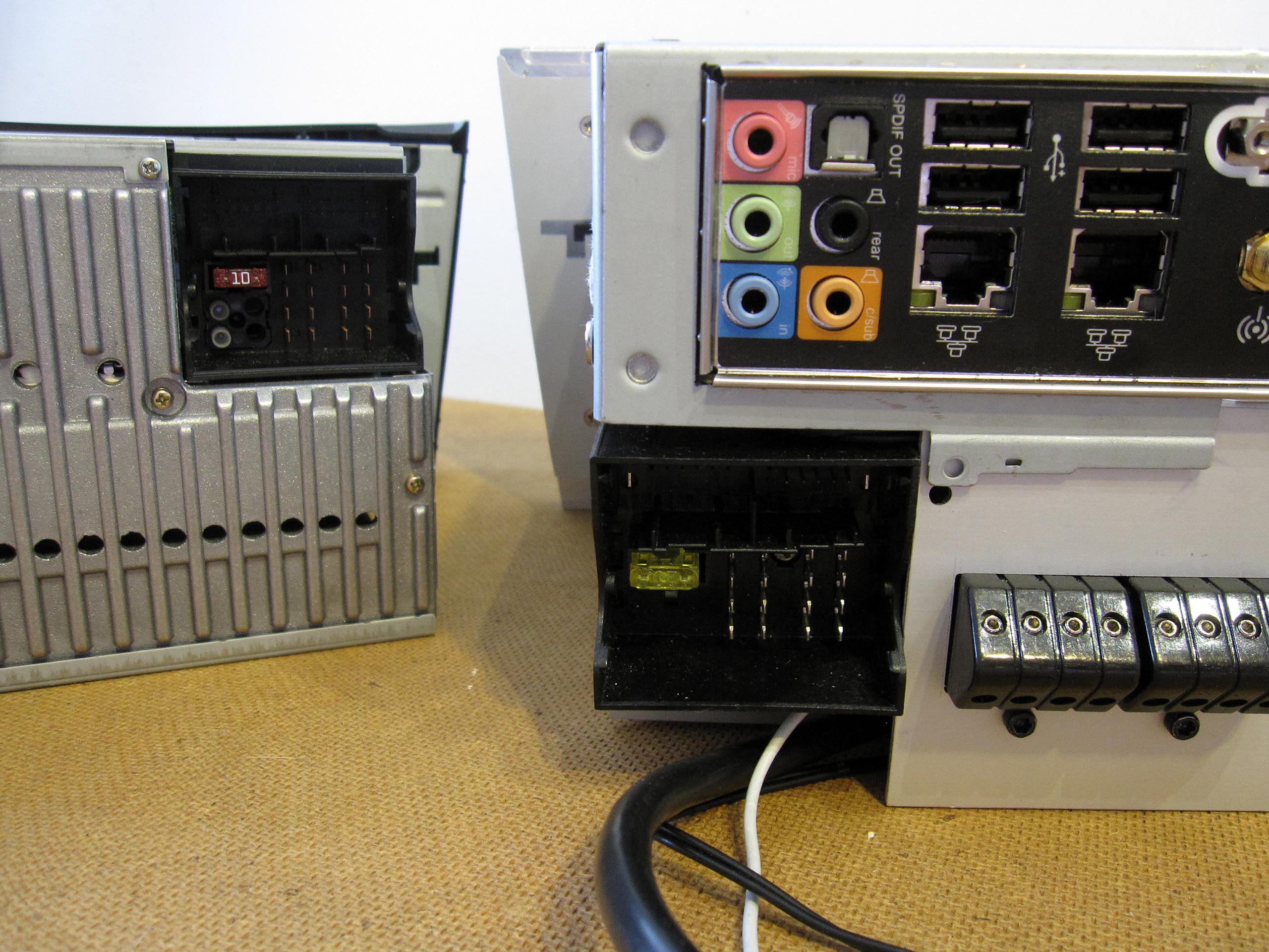
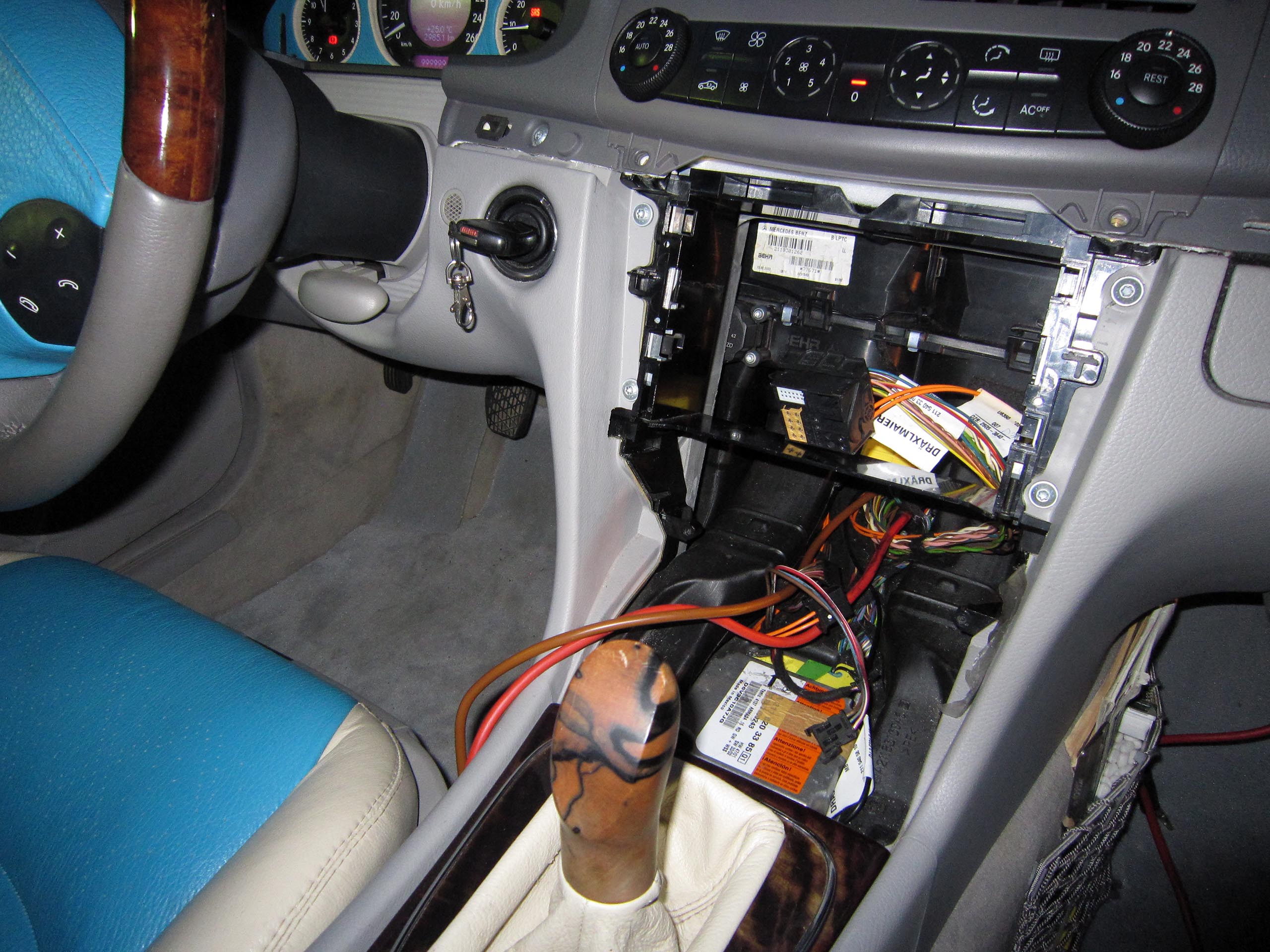
I drive a pre-facelift station wagon model. In this version, the Audio Gateway (AGW) control unit is integrated into the Audio 20 and not installed separately in the trunk. Therefore, the wiring runs from the speakers directly to the head unit in the center console. The ISO (Quadlock) connector also includes CAN Bus and several other wires. Next to the CAN-B connector there was an unused slot. I purchased a suitable MOST Quadlock ISO connector and contacts from vw-ma.ju@web.de. Now I can use 24 contacts in both connectors, for example to connect RS232, CAN Bus, and the power button.
The Audio 20 also controls the motorized cover of the internal storage compartment beneath the audio system.
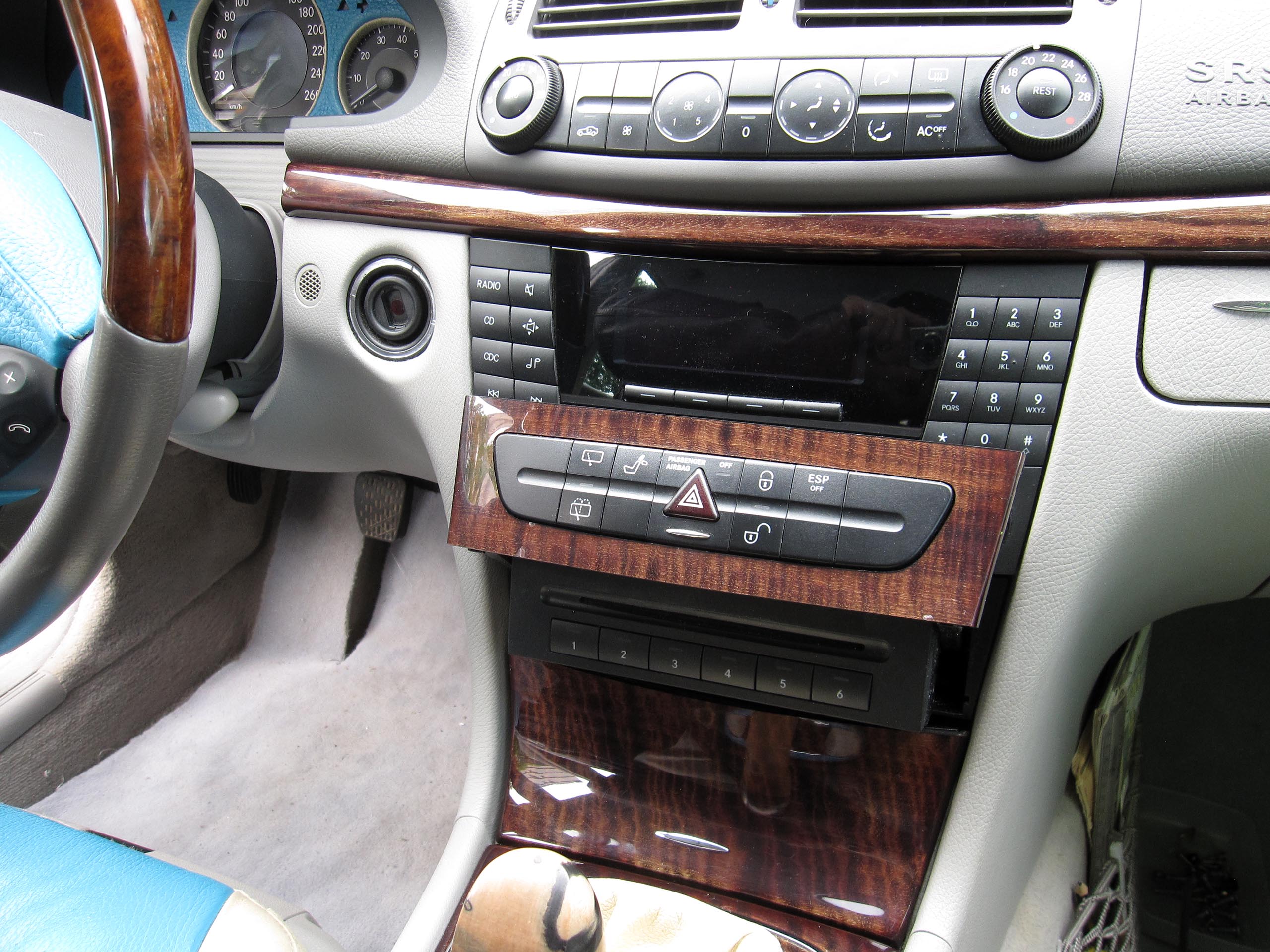
The slot is slightly taller than 2-DIN. The mounting of the car radio is specific, and the radio’s front panel is shaped to match the center console, with curved vertical and horizontal lines.
The wooden trim strip above the head unit can be easily removed, providing a bit more space at the top for the CarPC.
Behind the button panel below the head unit there is a storage compartment. After pressing a button, the cover slides forward and lifts upward. Inside is a six-CD changer, which is no longer needed and can be removed.
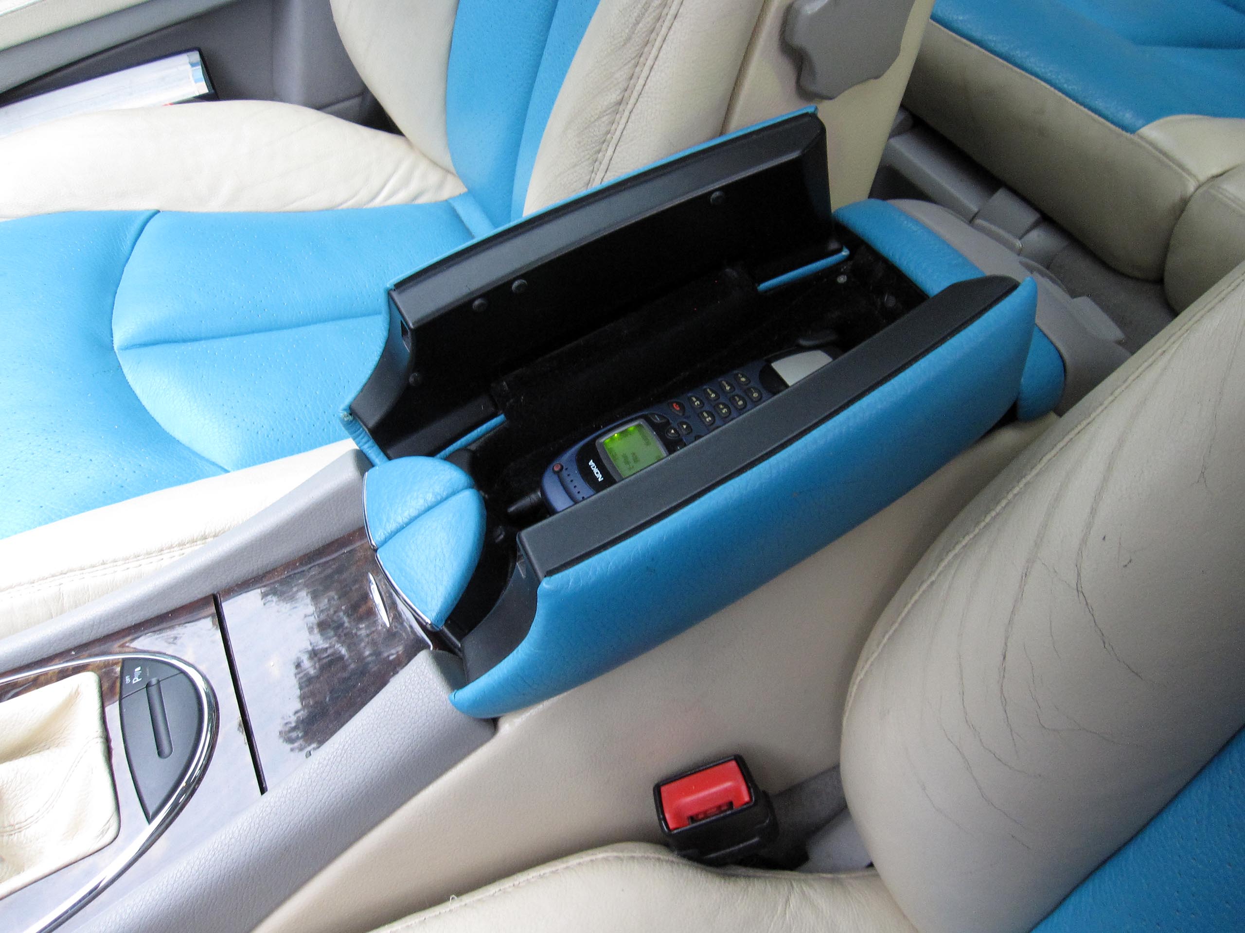
The MOST bus, as well as the module in the armrest with a cradle for a mobile phone used for hands-free calling, are also unnecessary for me and will be removed. The motherboard already has Bluetooth.
I would like to make as few visible modifications to the car as possible. The freed-up space in the center console should be fully utilized, so the display should be chosen with the maximum possible size. A 10.1-inch screen fits perfectly here. As a result, the front panel sits about 14 mm lower compared to the Audio 20. I would also use the compartment beneath the audio system, since the front panel will change anyway, but the modifications will be limited to this. The upper wooden trim and the ashtray remain unchanged.
The total power consumption of the system should be low. Each component must operate efficiently. The audio amplifier has an efficiency of 84.3%. The higher the efficiency, the less heat is generated during operation.
Technical Data:
Boot Time:
Power supply response time: 3 seconds
Operating system boot time: 14 seconds
Music starts playing after a further 6 seconds
Total boot time: 23 seconds
Power Consumption at 13V:
Display: 0.6 A
Total: 3.3 A during normal use, 6.5 A under load, 8.5 A short-term peak
Dimensions and Weight:
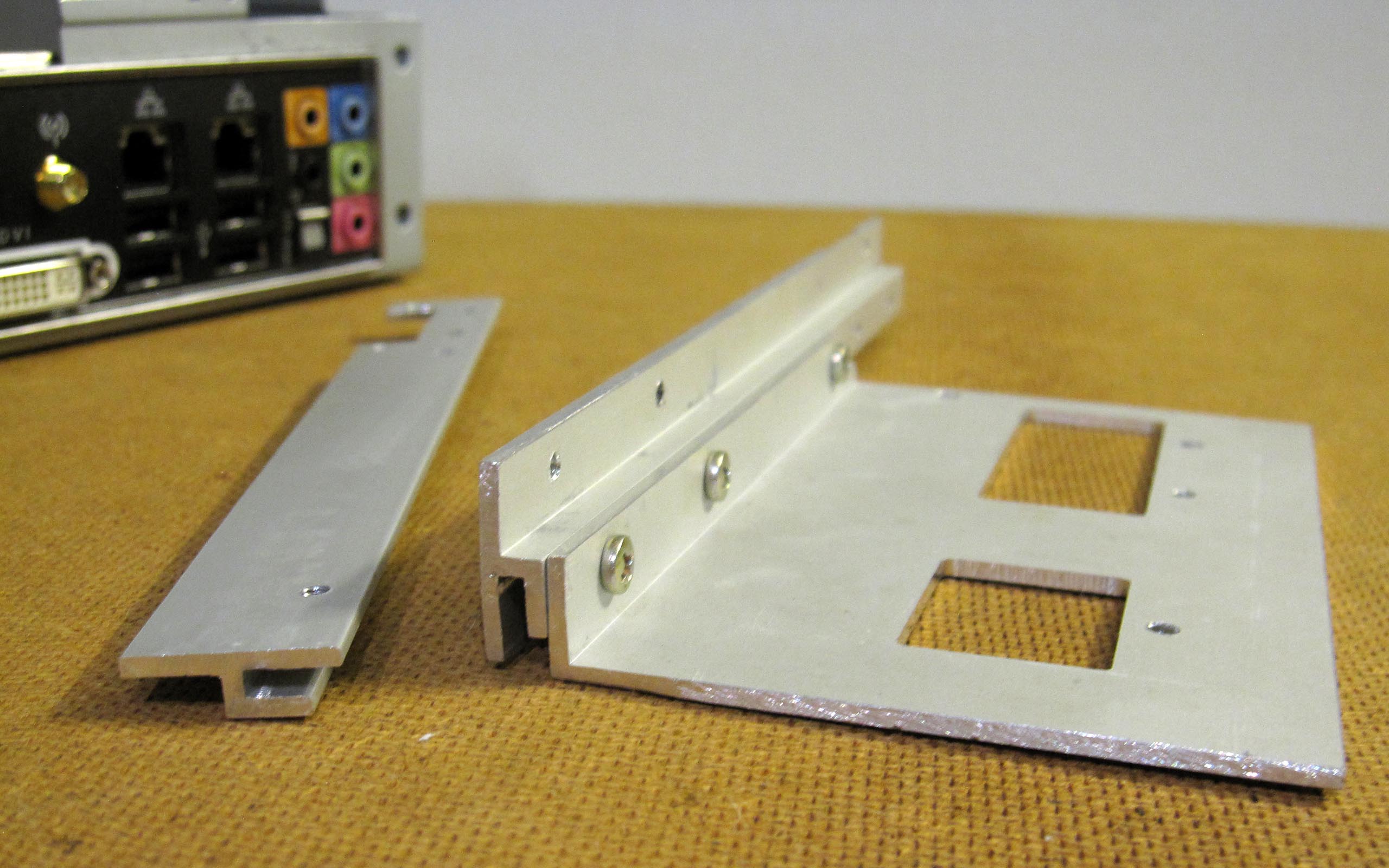
Front Panel
Width: 263 mm (same as the original head unit)
Depth: 25 mm (same as the original head unit)
Height: 146 mm (extends approx. 14 mm beyond the original dimensions at the bottom)
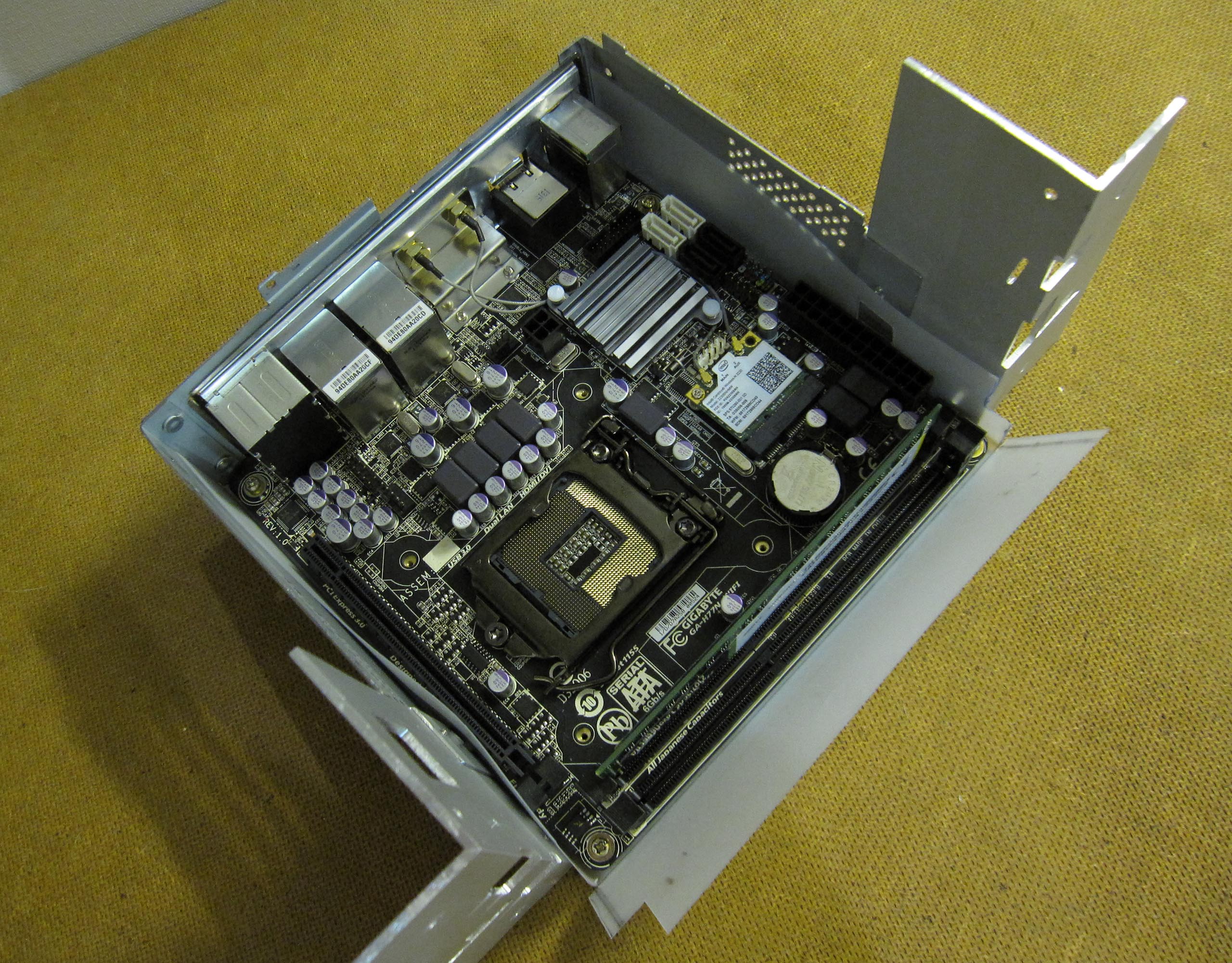
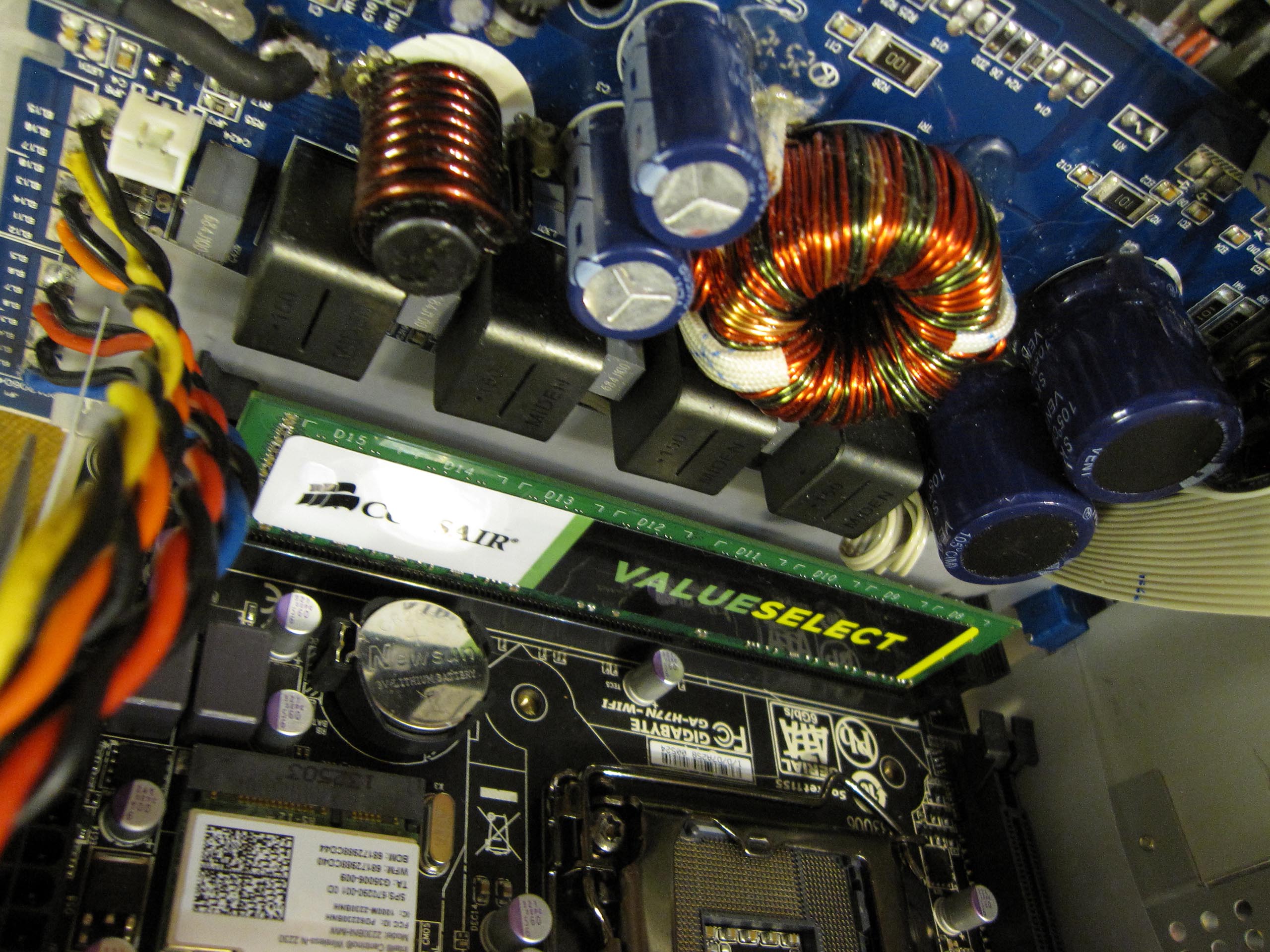
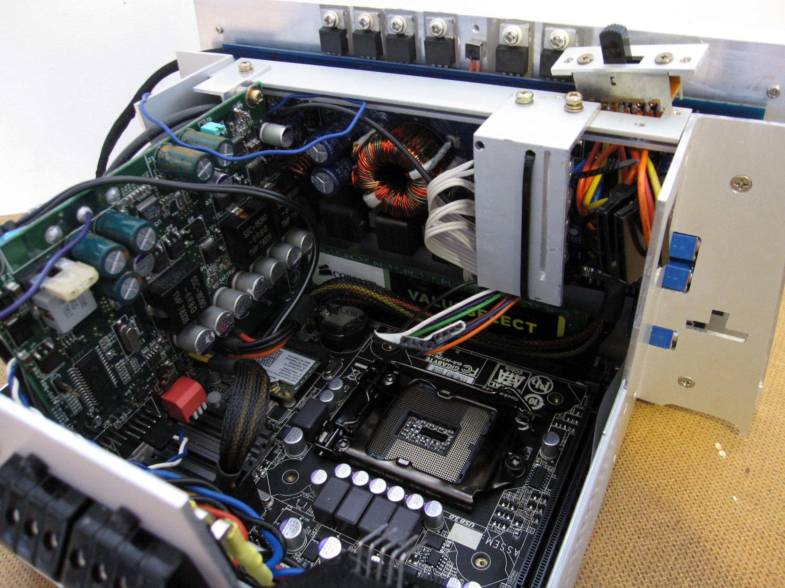
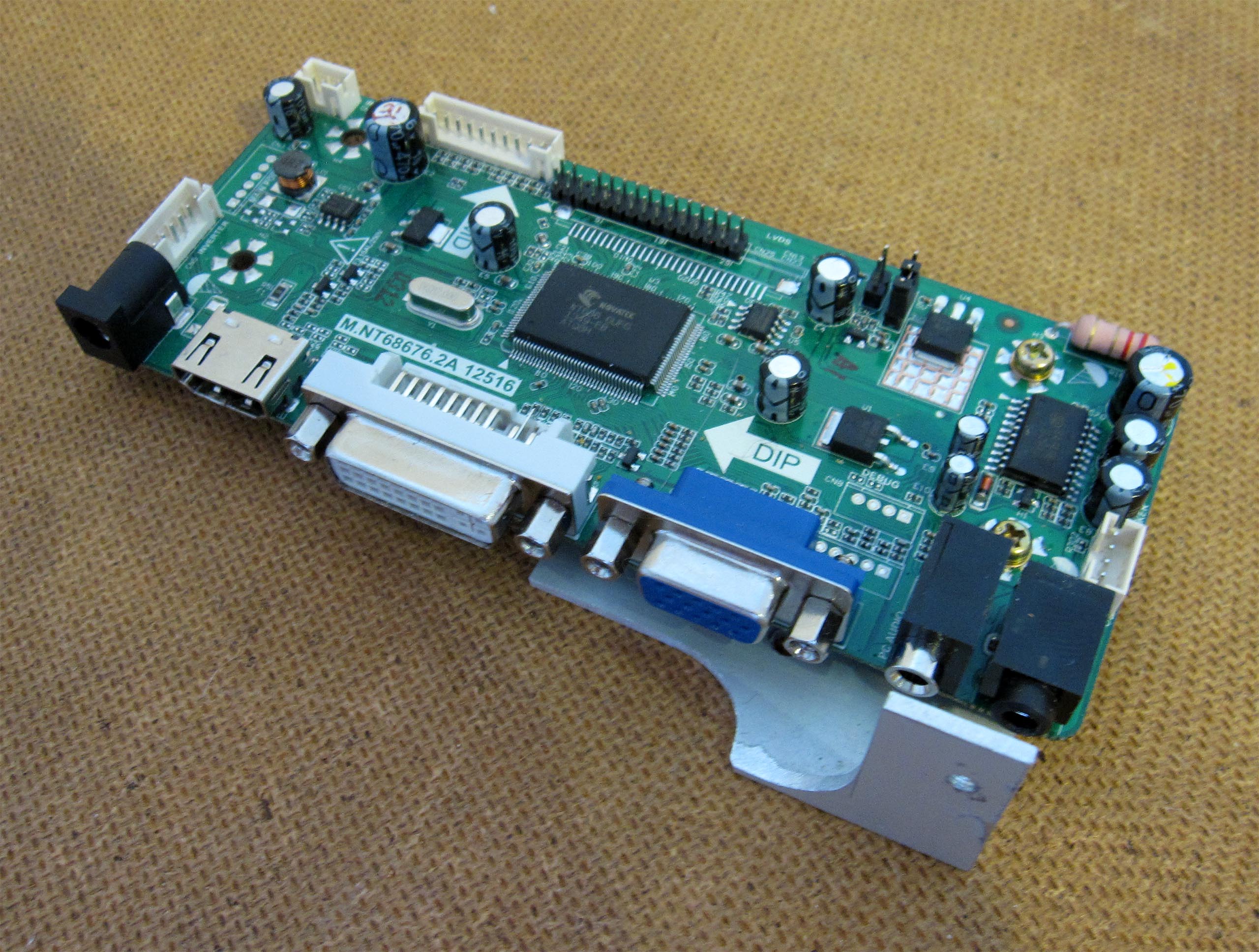
I did not modify the motherboard. The choice fell on this model because of the position of the 24-pin connector and the memory slots.
The motherboard is equipped with an Intel Core i5-2500K processor (6M cache, 3.30 GHz) with a TDP of 95 W. Due to structural constraints, the board must be installed upside down. As a result, the heat sink is suspended. Its low weight places only minimal stress on the mounting. Vibrations are an important factor in a vehicle. All screws must withstand long-term loads.
Graphics Card
I use the graphics unit integrated into the processor. However, when I install the drivers, the HDMI connector on the motherboard stops working. Testing with another motherboard confirmed this issue. With an external graphics card and installed drivers, the display works via HDMI cable. After contacting Intel customer service, it was assumed that the Intel HD Graphics 3000 had a defect. I then purchased an Intel Core i7-3770K with Intel HD Graphics 4000. Now the HDMI outputs on the GA-H77N-WIFI function correctly. However, they no longer work on the other motherboard. When attempting to install the drivers, the operating system freezes. Interestingly, HDMI on the external graphics card in combination with the Intel Core i7-3770K also does not function. I updated the BIOS on that slightly older motherboard, so the new processor should be supported. I connected the display via HDMI using a custom-made cable. The HDMI connector is relatively small and fits perfectly into the PC.
RAM and Hard Drives
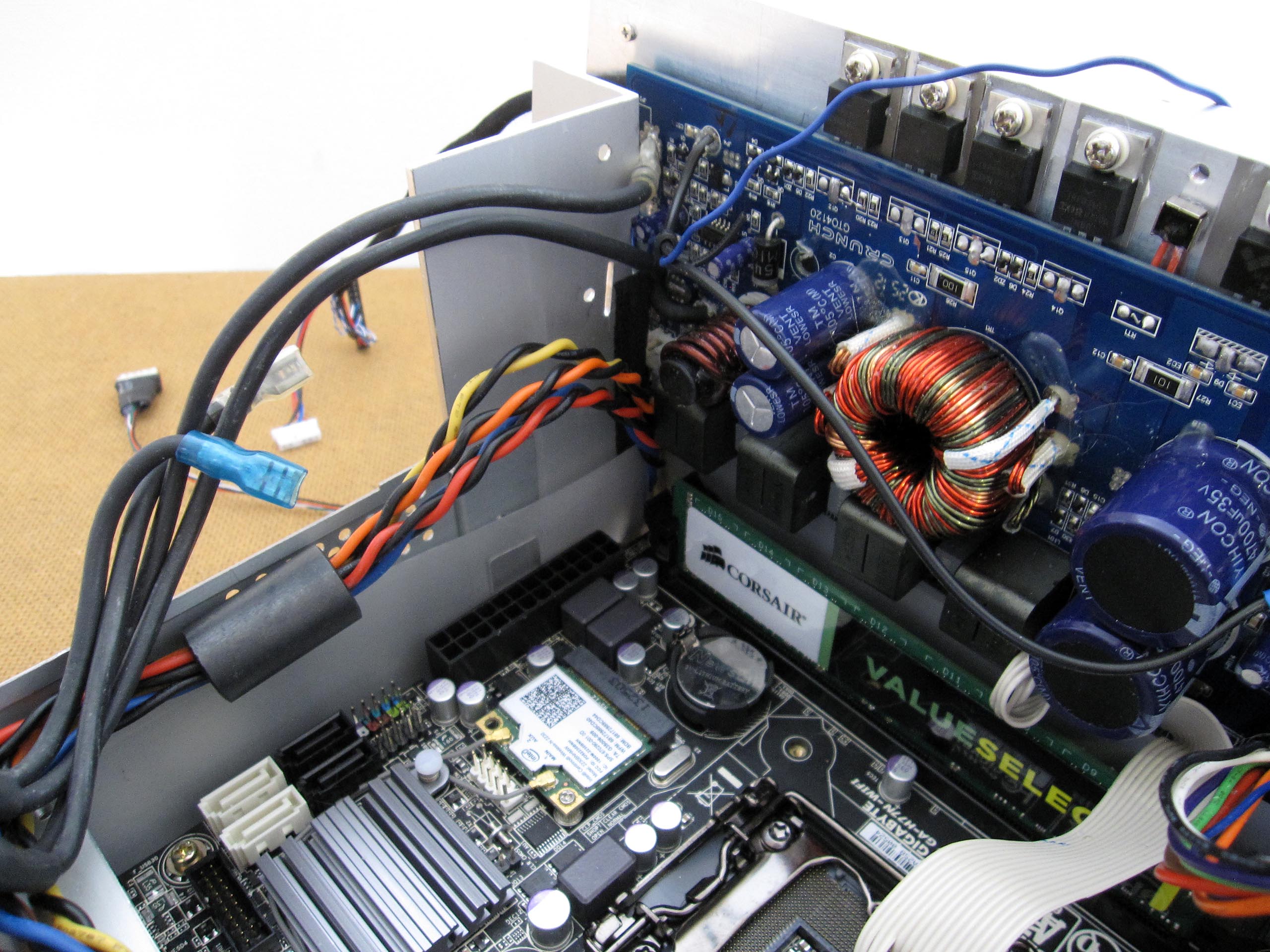
The RAM is located next to the audio amplifier. The motherboard has two memory slots. At the moment, only one Corsair CMV8GX3M1A1333C9 with 8 GB is installed.
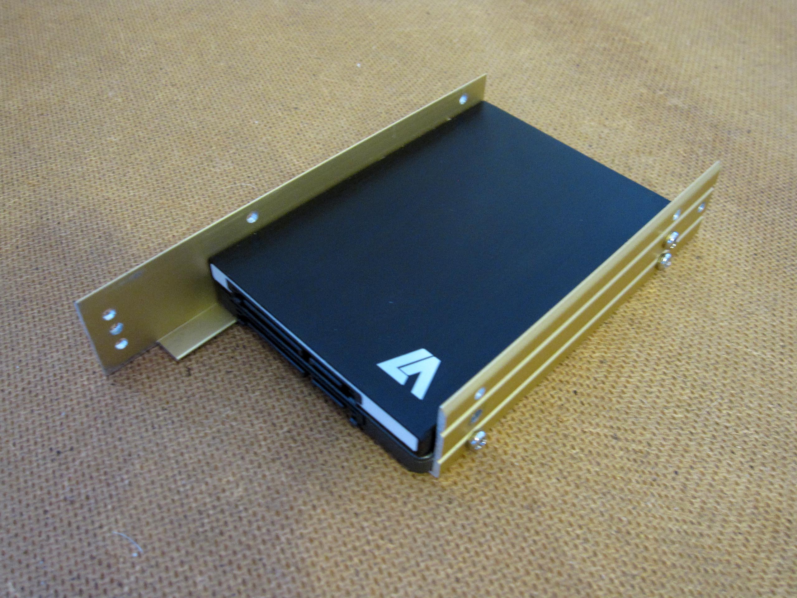
I installed two hard drives. Space is also reserved for a third one. I supplied power to the hard drives using a switch (4x ON/ON). This allows me to activate only one hard drive at a time. Since this car computer is a prototype, I can install two operating systems and test them in parallel without having to dismantle the entire computer.
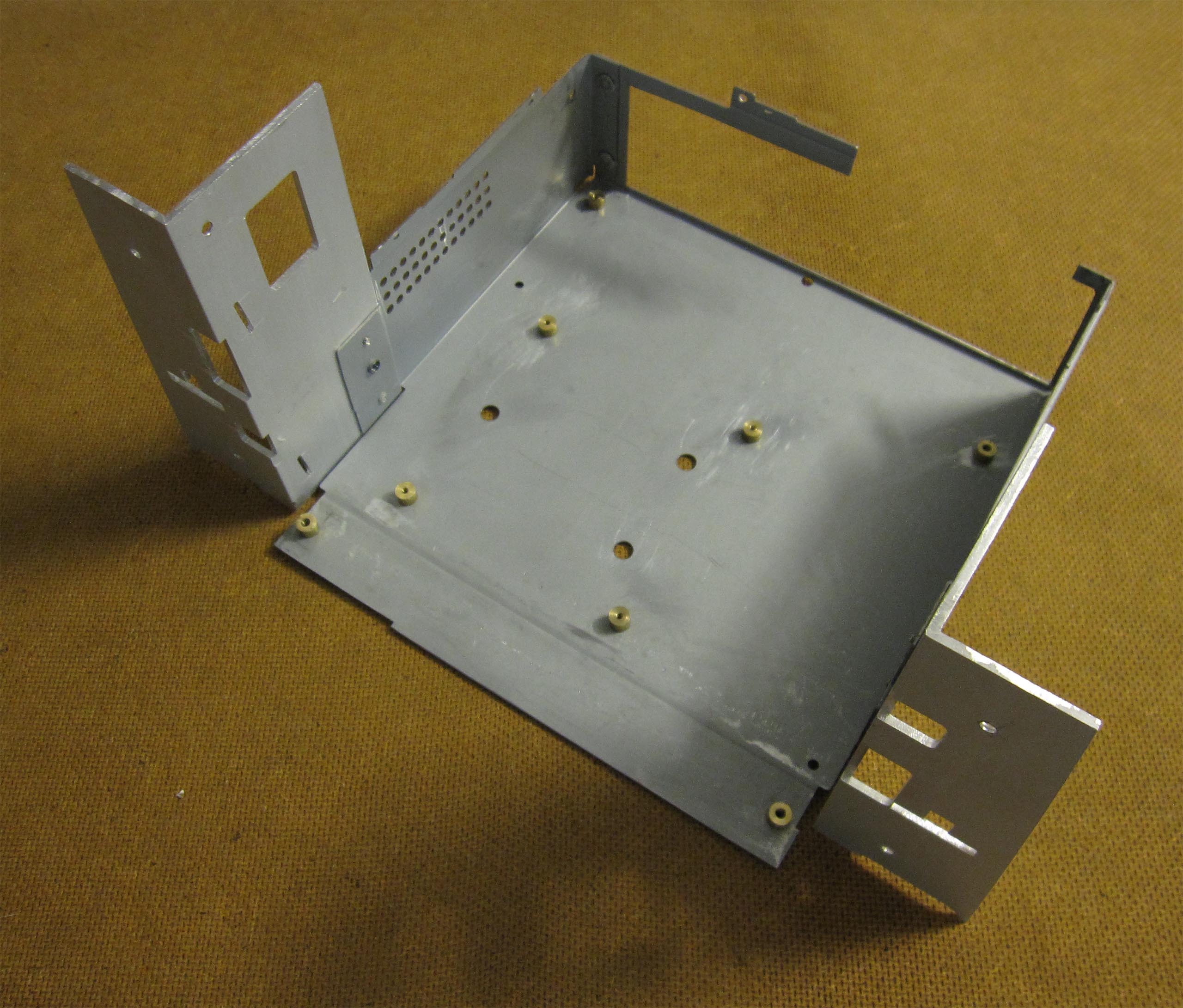
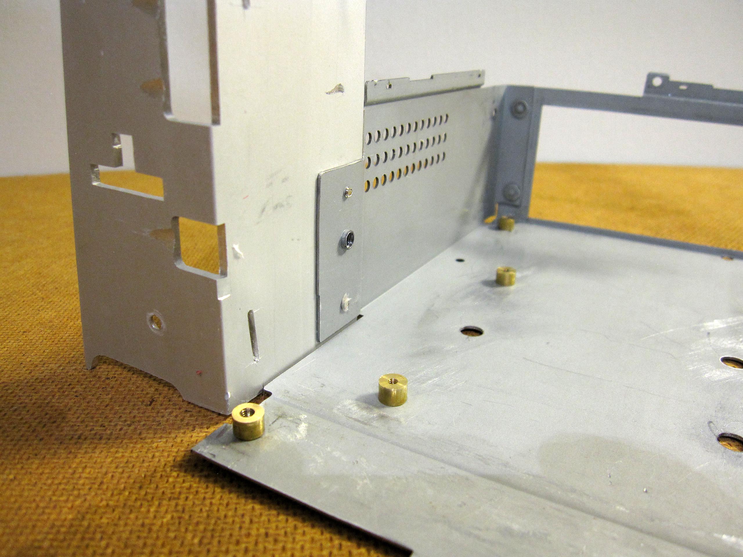
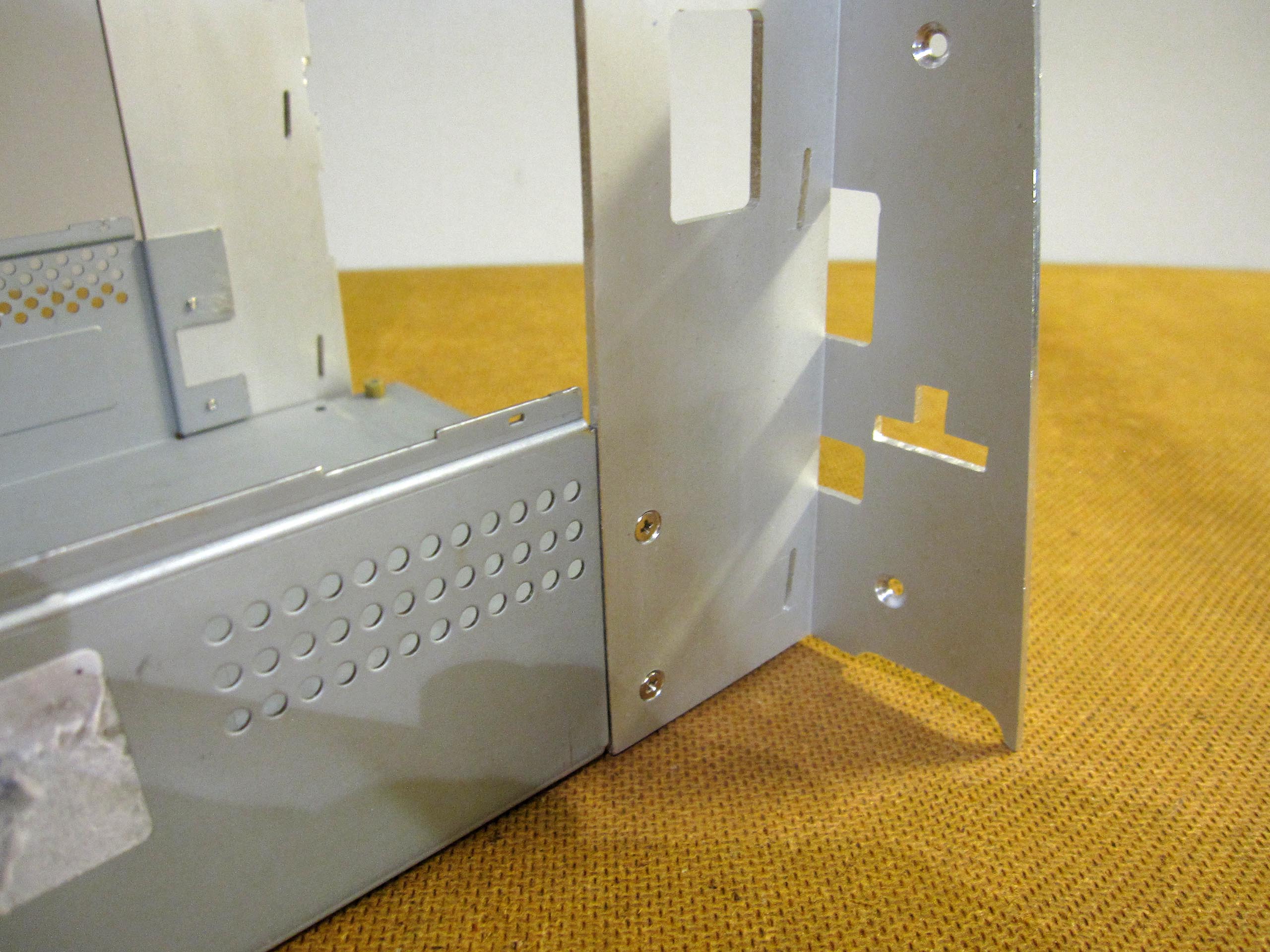
Housing
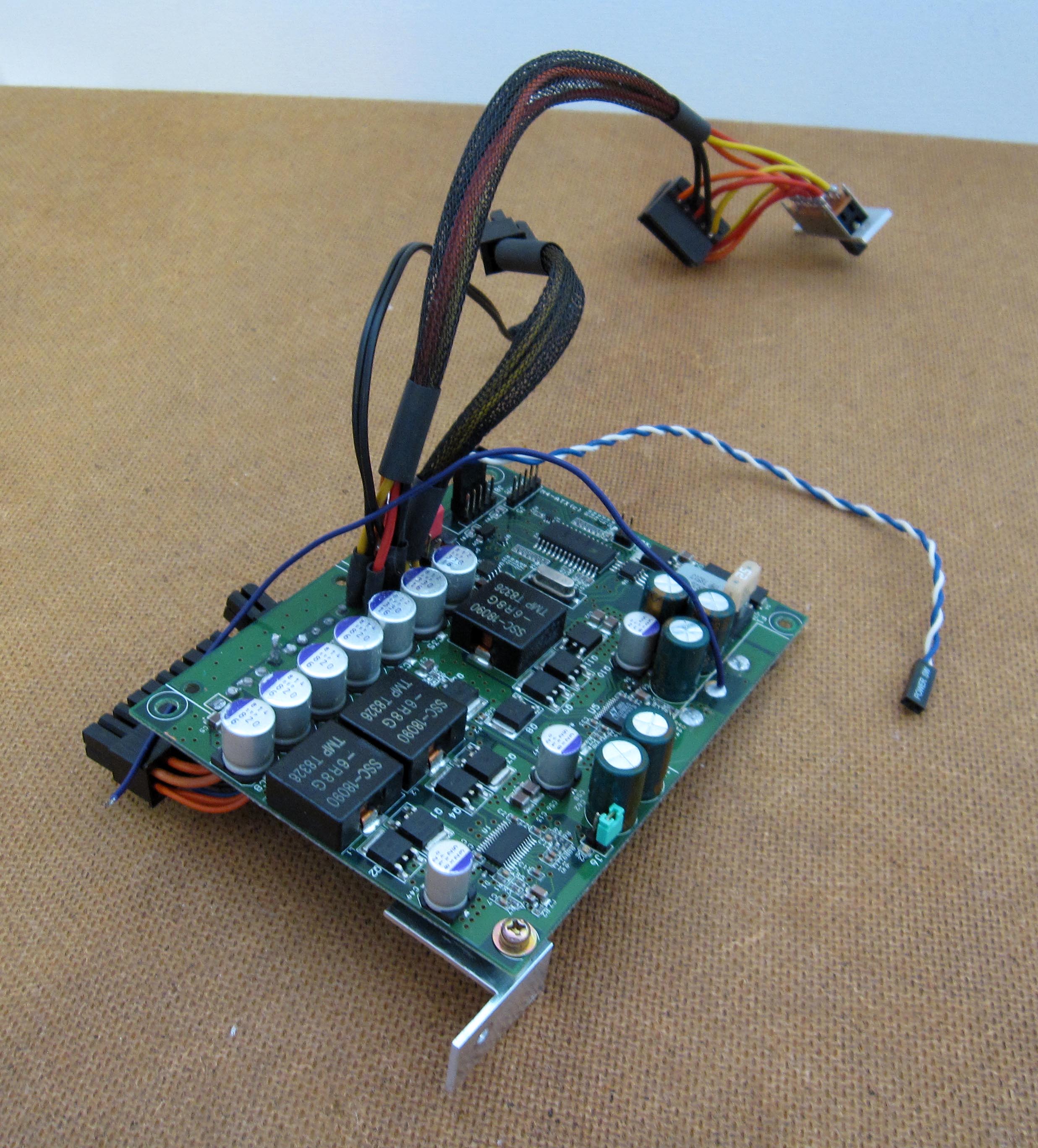
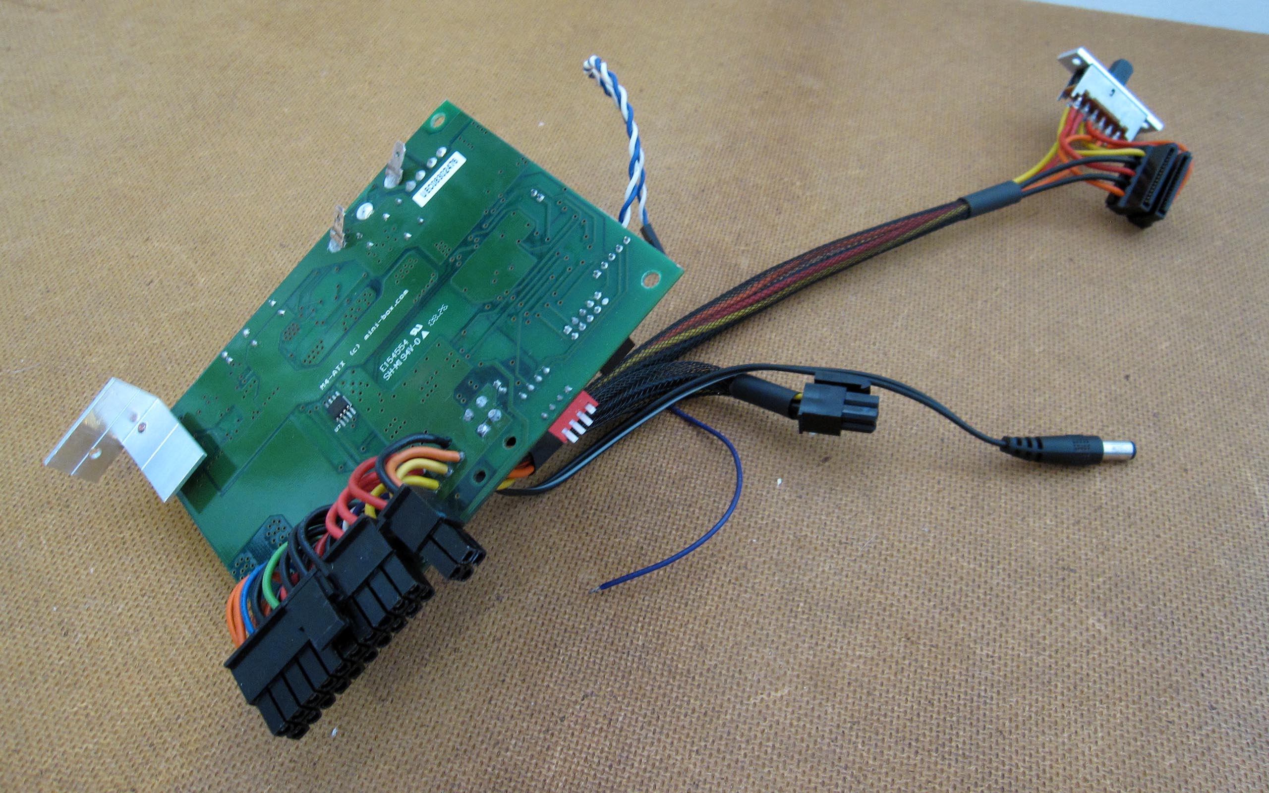
Power Supply M4-ATX
I had to resolder the power supply; I redesigned the 24-pin connector instead of using the standard configuration. Since this step was quite complex, I would suggest the following idea to the manufacturer: as everyone builds their AutoPC differently, it would be better to supply the board without a connector, allowing each user to solder a custom cable harness of the required length. Additionally, the board itself could be made smaller. Extra solder pads for GND, 3.3 V, 5 V, and 12 V would also be useful. In my case, for example, I could have securely soldered the hard drive power supply and the display controller board power supply directly.
The amplifier was clicking, so I had to find a way to eliminate the issue. The power supply has a built-in anti-pop function. The amplifier is switched on. In any case, the Crunch amplifier has an automatic switching function. If a signal is present at the high-level inputs, the amplifier switches on automatically. In this case, the remote contact does not work. Since the amplifier is connected via RCA (Cinch), it should not have switched on at all. Therefore, I tried replacing the cable to the additional board. A wire with a smaller cross-section produced the desired result. I then set the delayed turn-on parameter on the power supply to 16 seconds. As a result, the amplifier now switches on later than the audio drivers are loaded in the operating system.
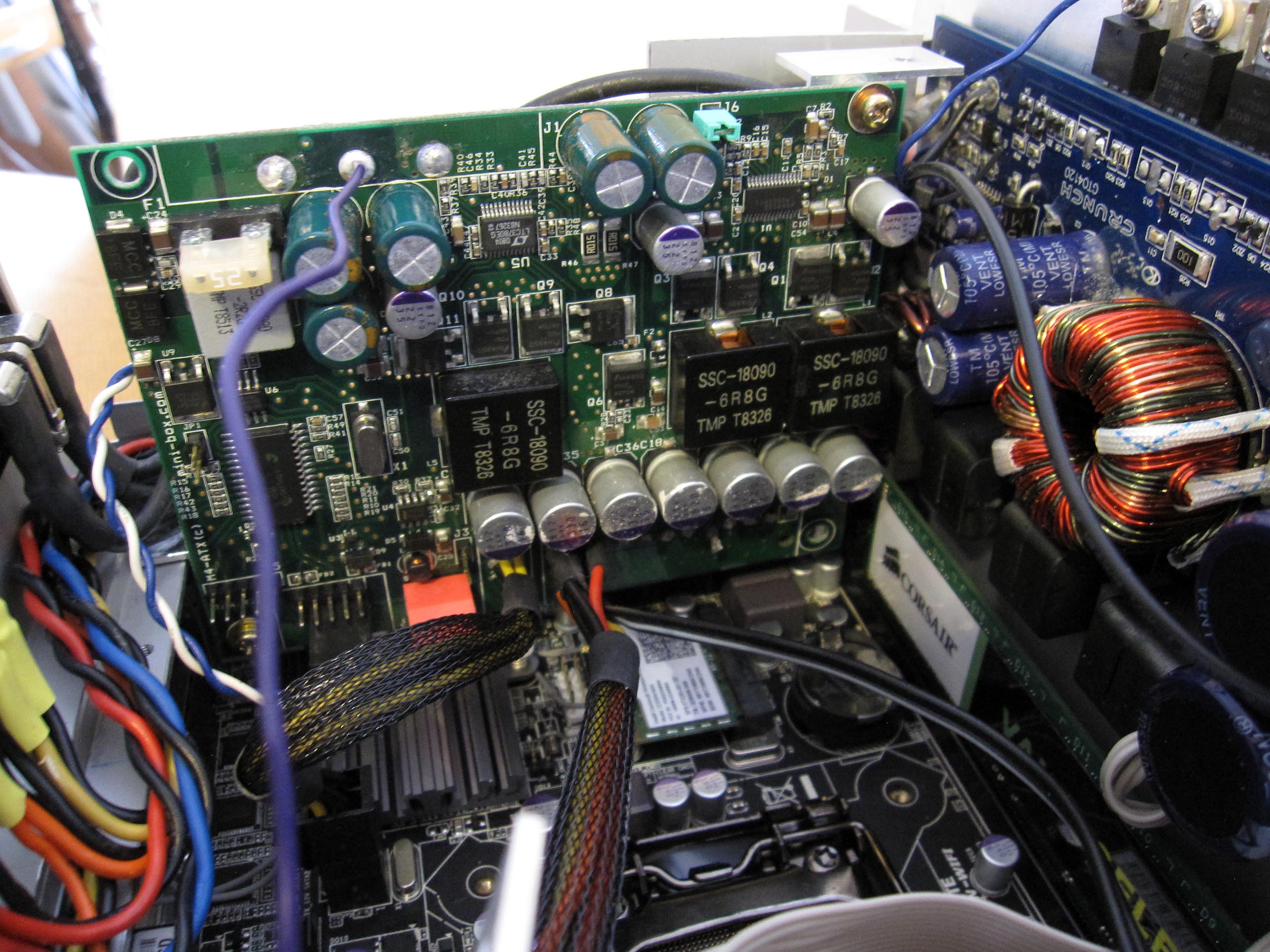
Amplifier Crunch GTO 4120
Since I did not want to use an external amplifier but rather one that could be integrated into the head unit, I looked for a compact amplifier. The Crunch GTO 4120 seemed to be a good choice. According to its technical specifications, the device also belongs to the HiFi class.
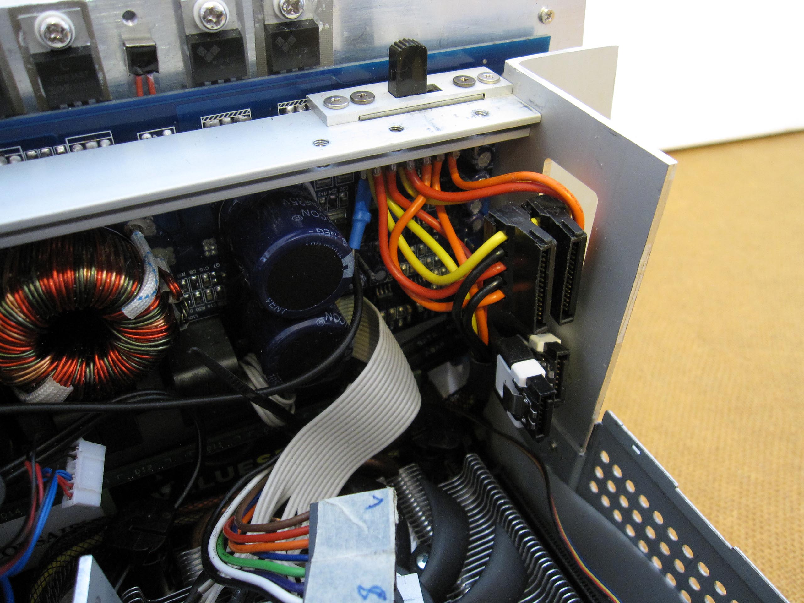
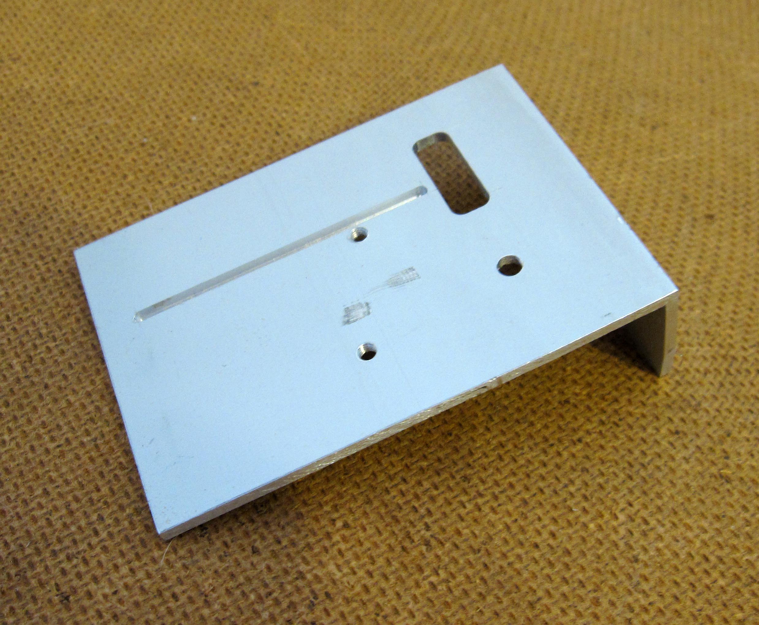
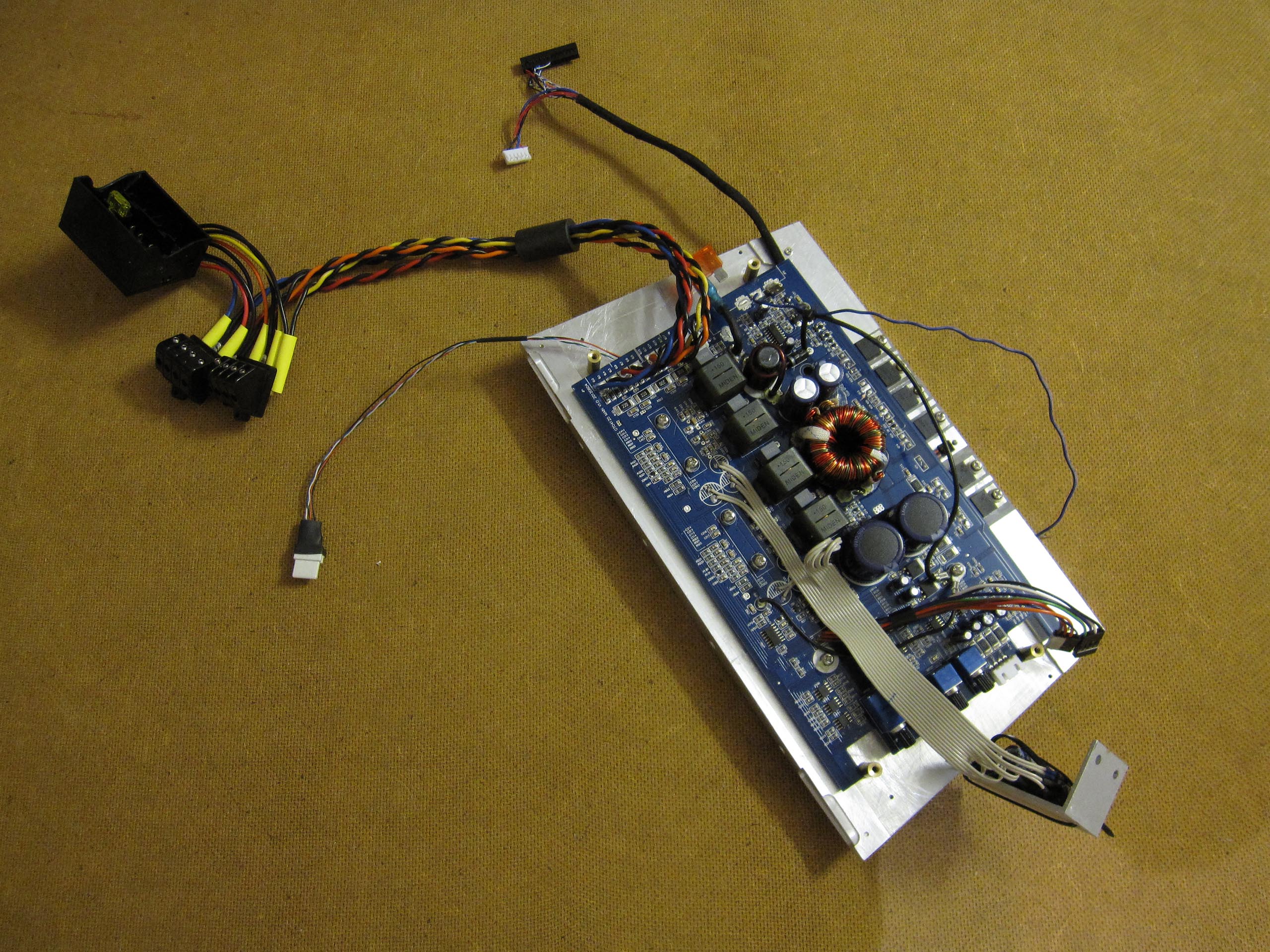
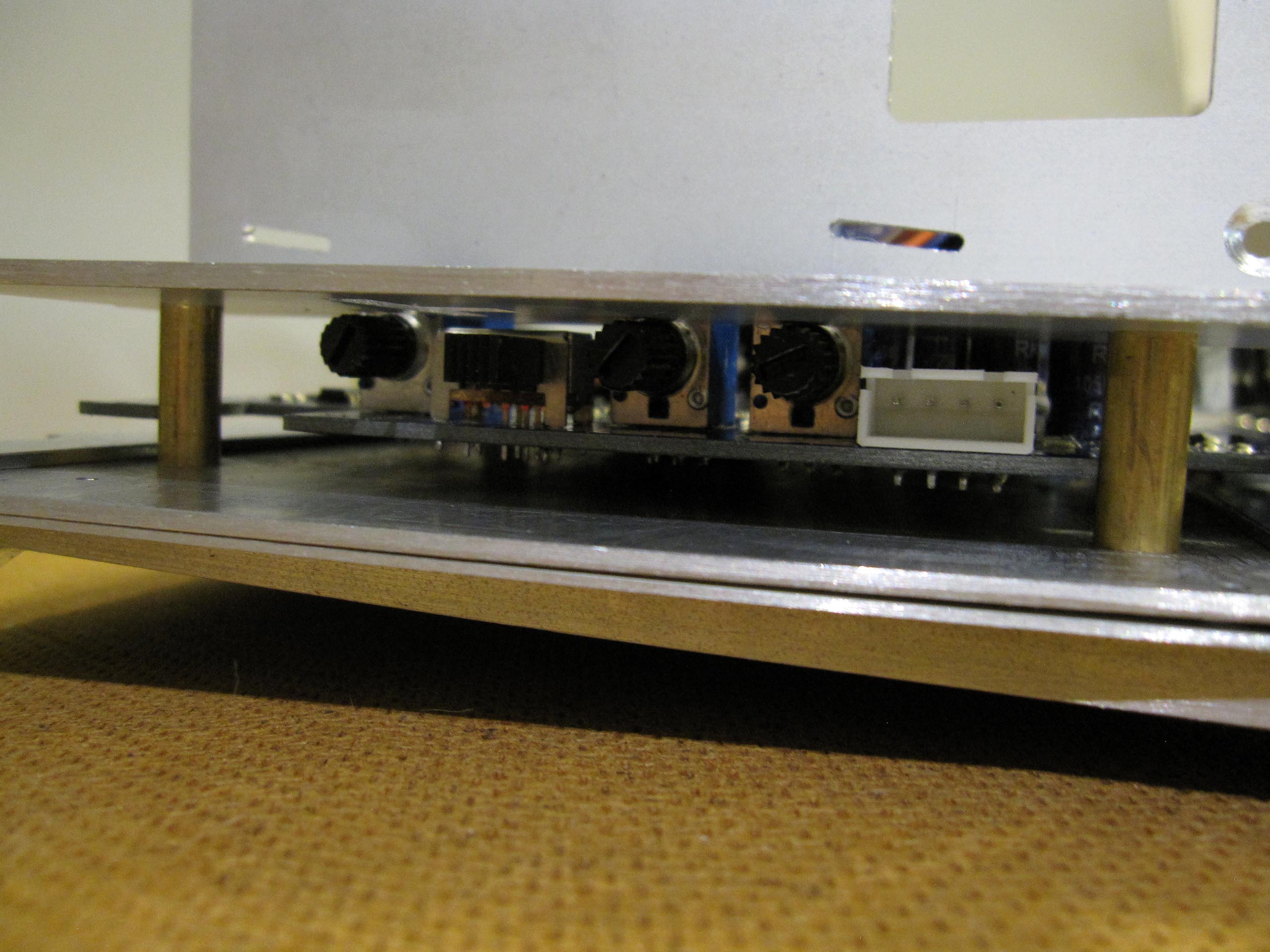
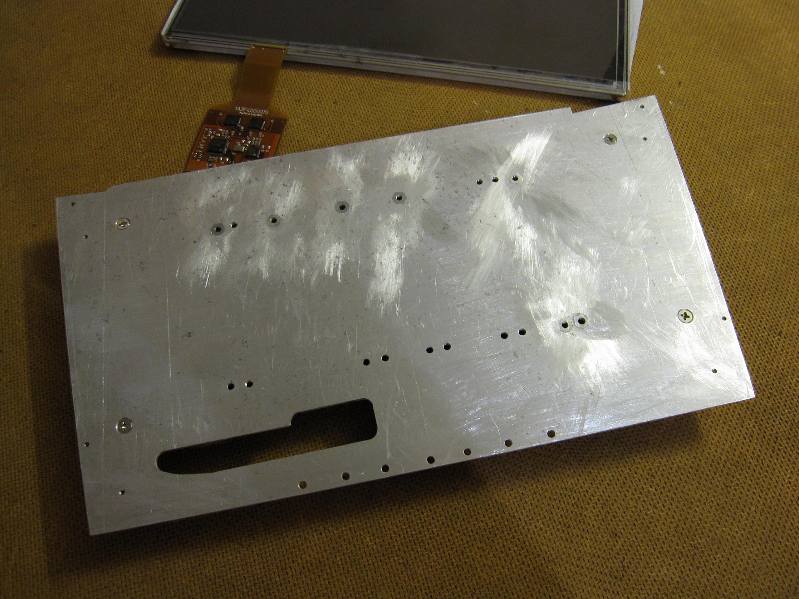
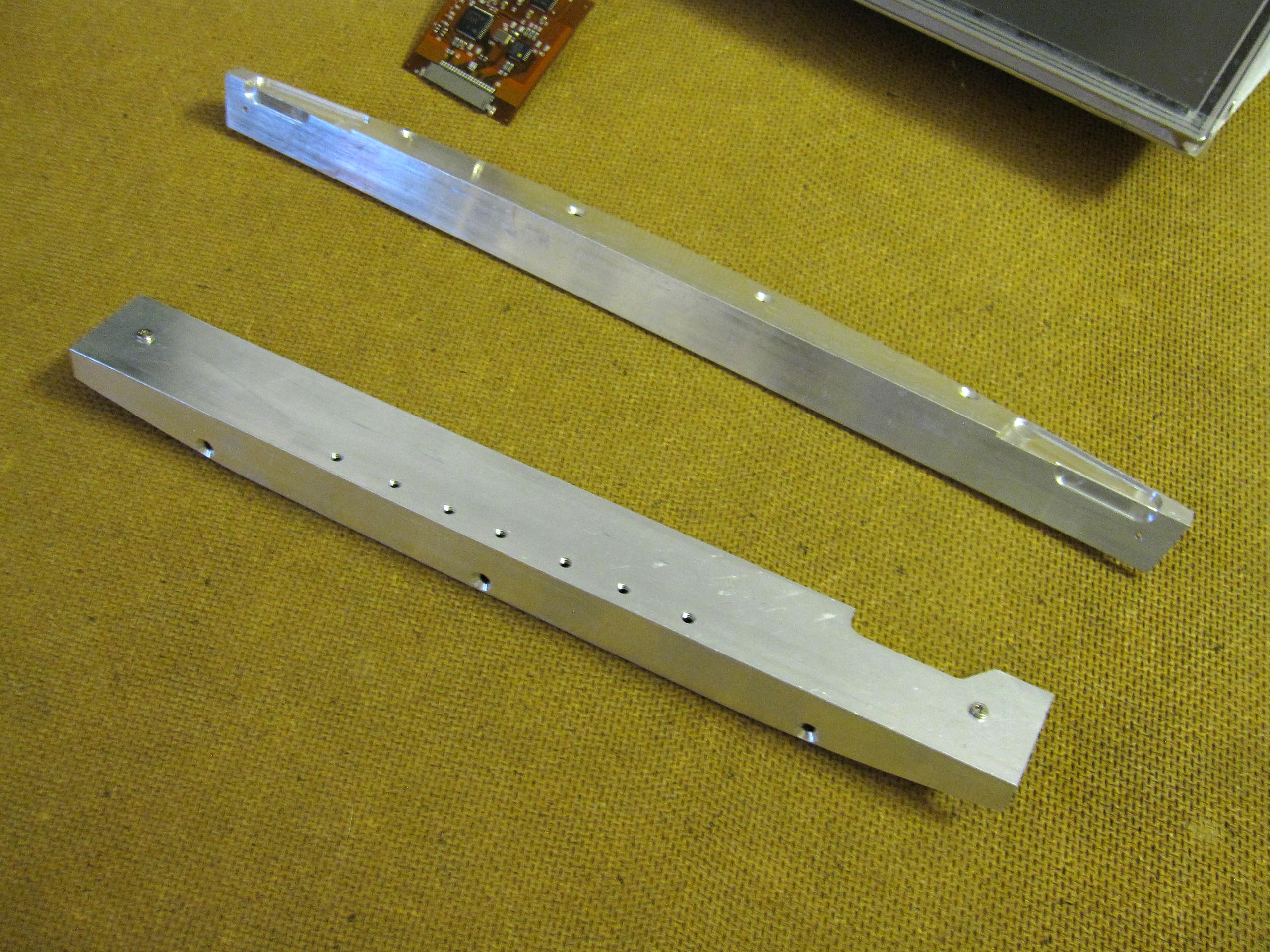
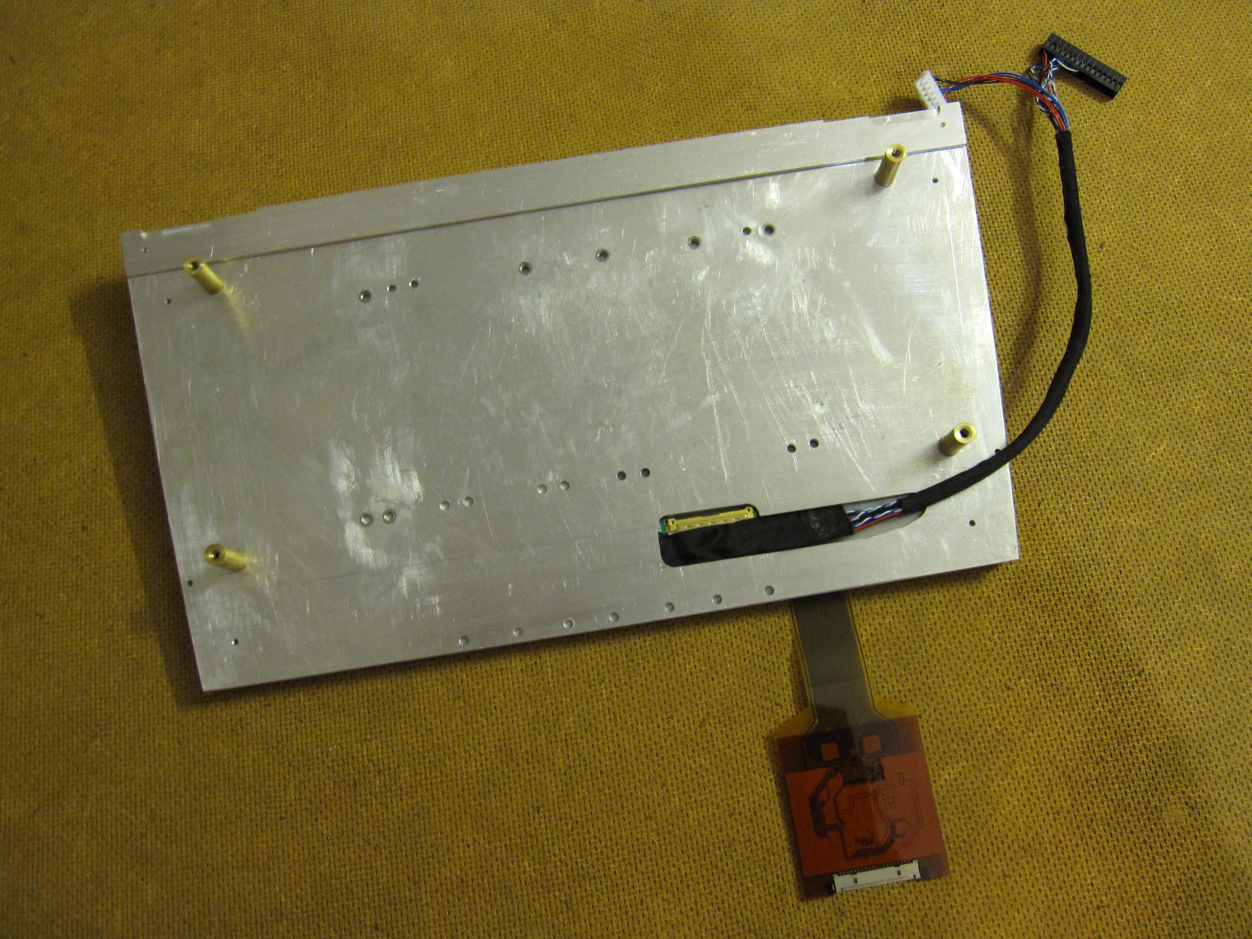
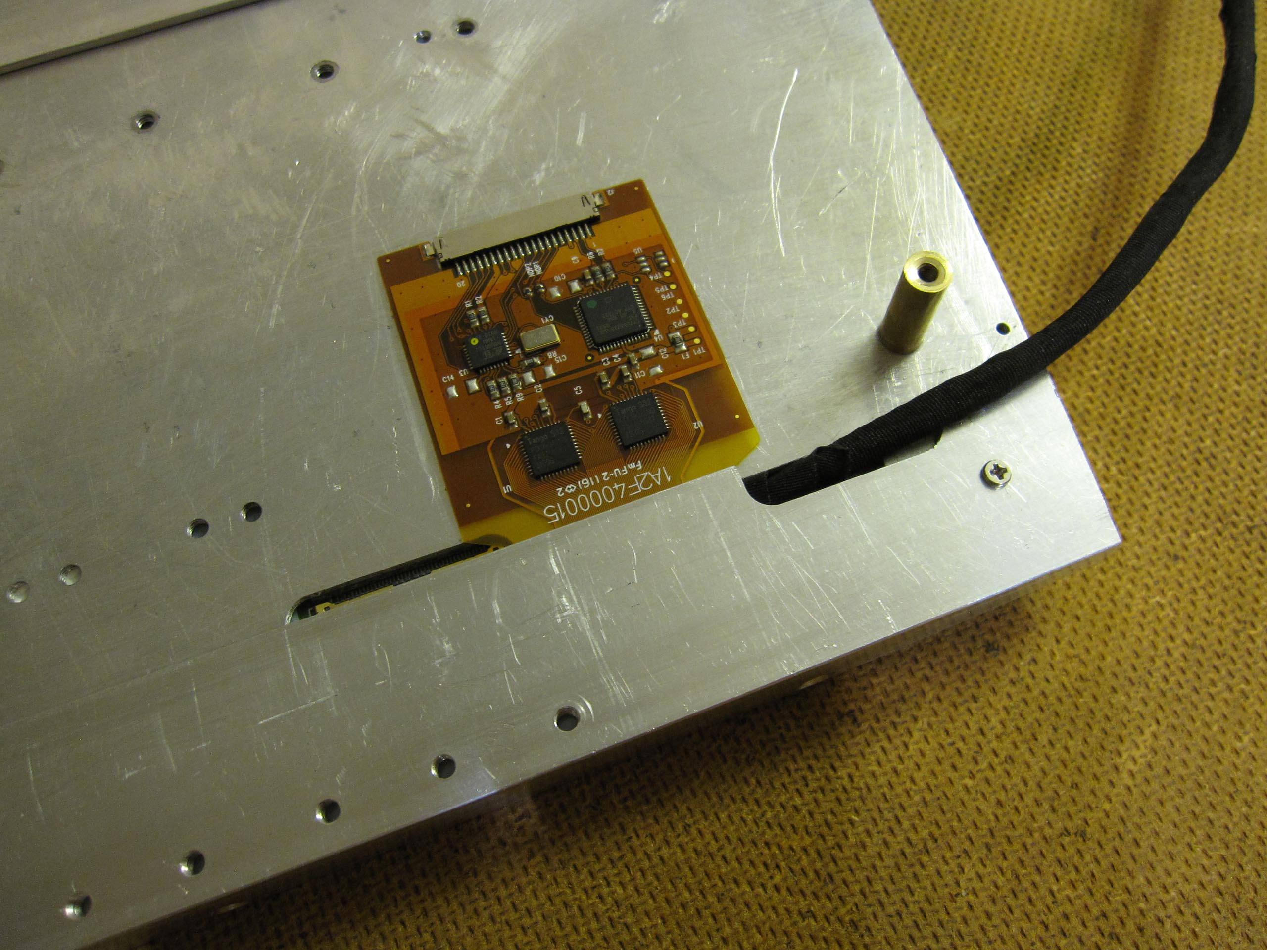
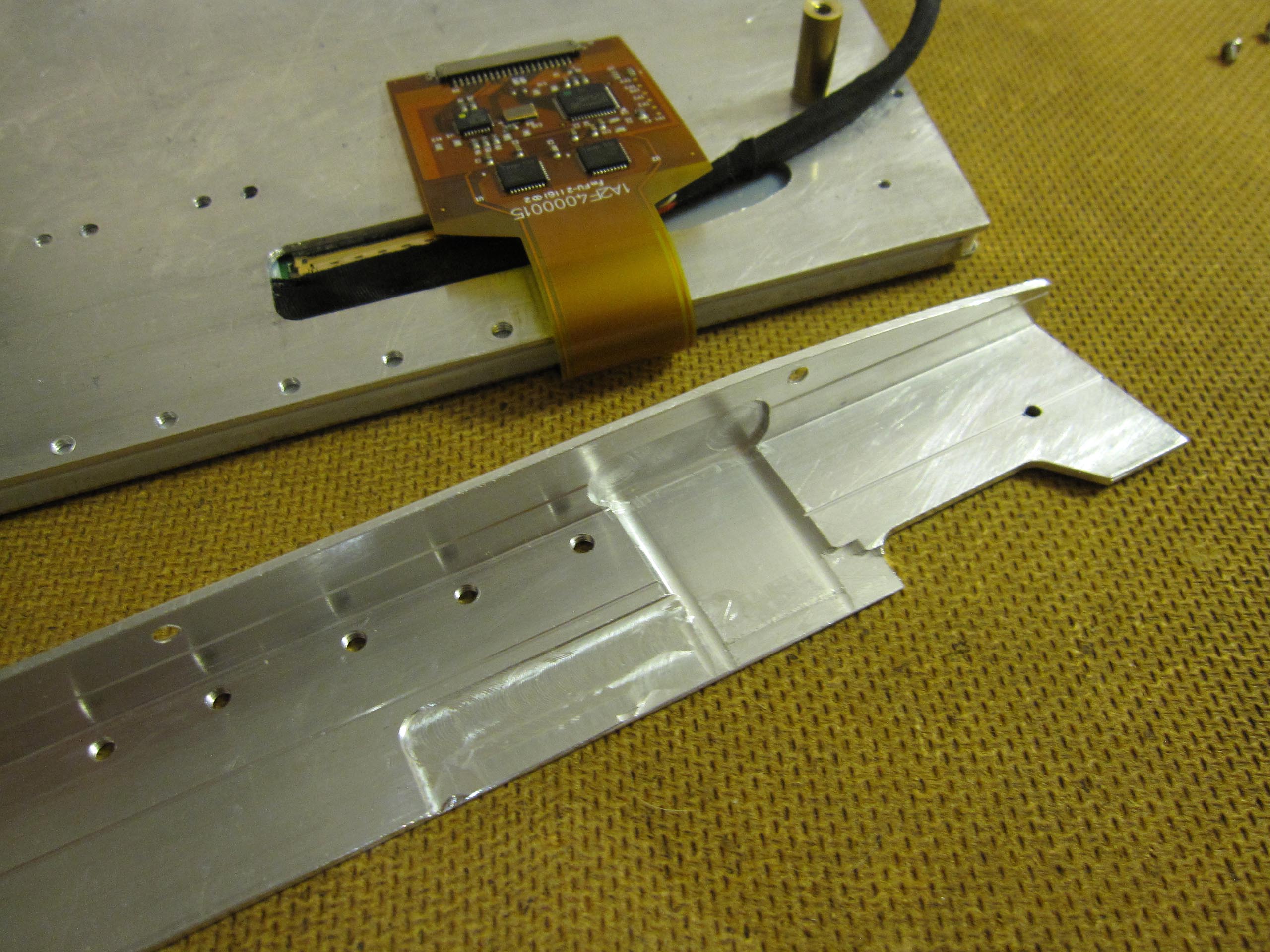
I mounted the main board on an aluminum plate behind the screen. In other words, the display is attached to one side of the aluminum plate and the amplifier to the other.
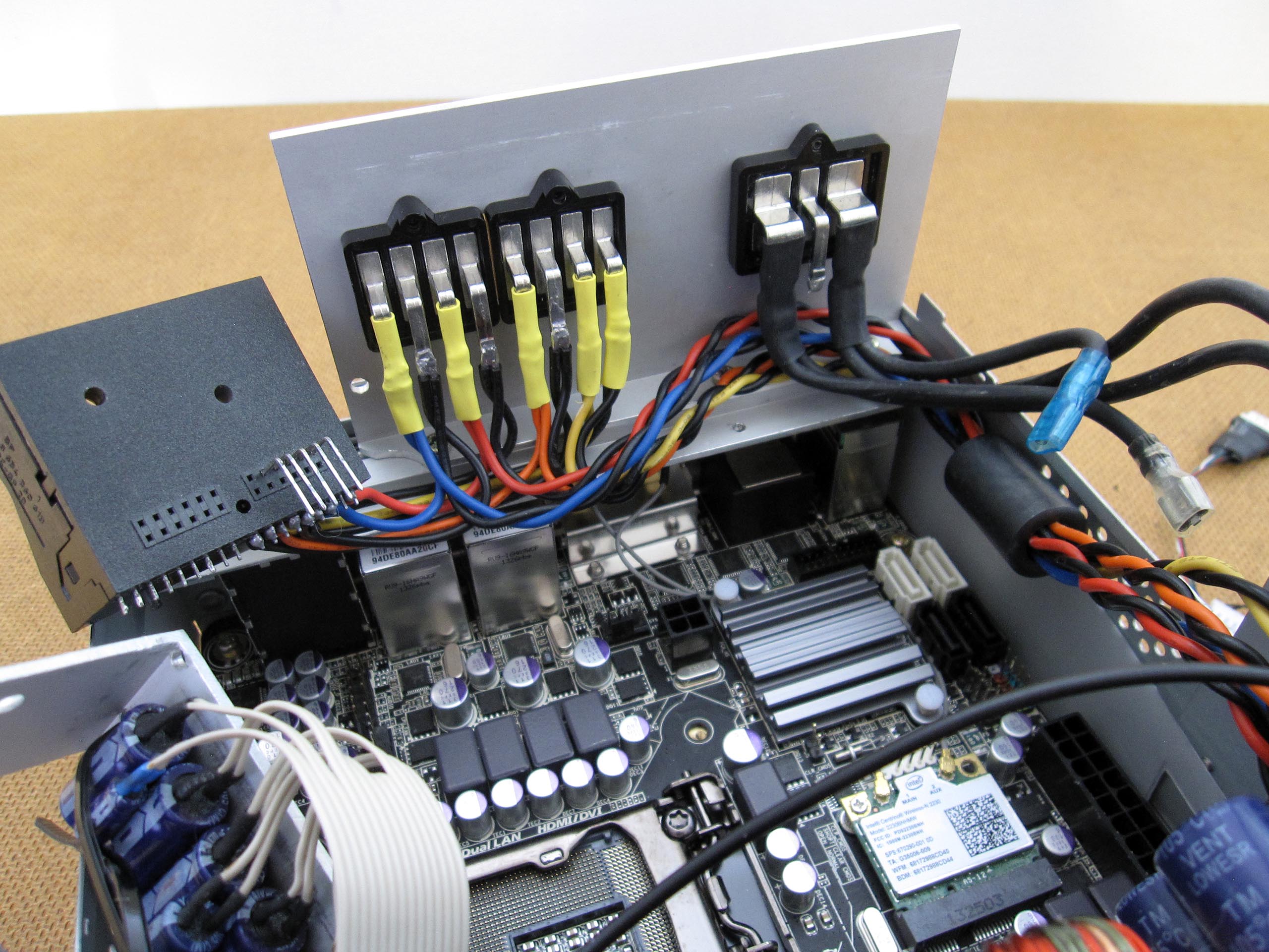
I resoldered and modified the power supply, fuse, LED indicators, and speaker connections. I also had to reposition the capacitors to ensure there was enough space for the RAM modules. I replaced the wires for the small board with longer ones. The capacitors and this board are mounted on an aluminum angle bracket. I desoldered two RCA sockets since they were not needed, which created additional space inside the housing.
Another important issue is avoiding humming noise that degrades sound quality. The problem may be caused by ground loops resulting from small differential voltages on the vehicle ground. Interference can also come from various vehicle components or from the Car-PC itself, as well as from incorrect wiring or insufficient insulation. The Car-PC should have only one ground connection to the vehicle. The computer housing must not touch the car body, even though the main amplifier board is mounted on rubber pads and bushings. It is important that power cables are routed separately from audio cables; crossing them at right angles is acceptable, as this prevents interference during audio transmission. The compartment where the Car-PC is installed is made of plastic, which minimizes potential noise sources. Since the motherboard and the integrated sound card are installed in the same housing as the audio amplifier, the connecting cables are relatively short. To be safe, I fitted the cables with ferrite rings.
The first tests were successful. Everything works on the desktop so far and without noise.
Display and Touchscreen:
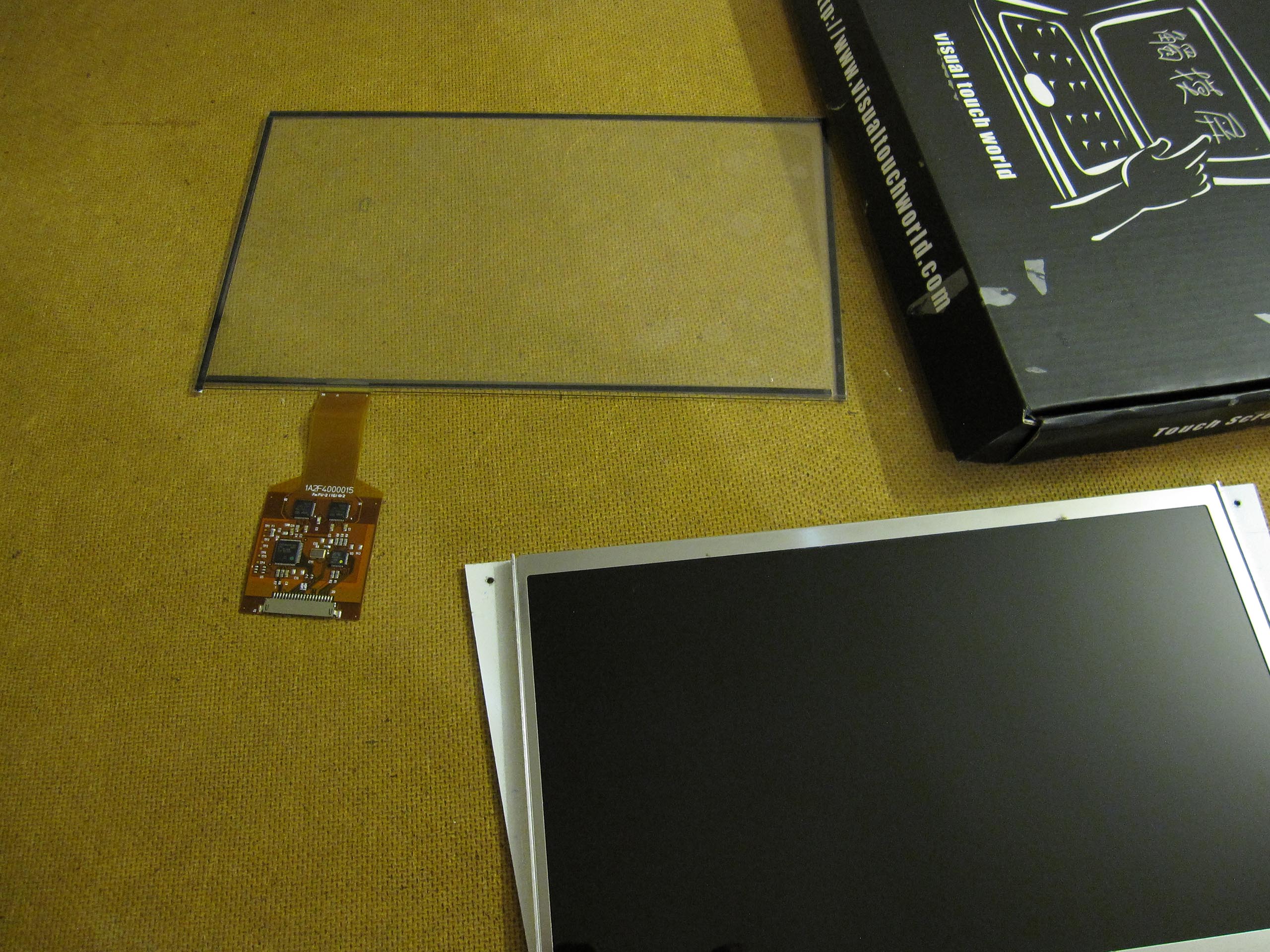
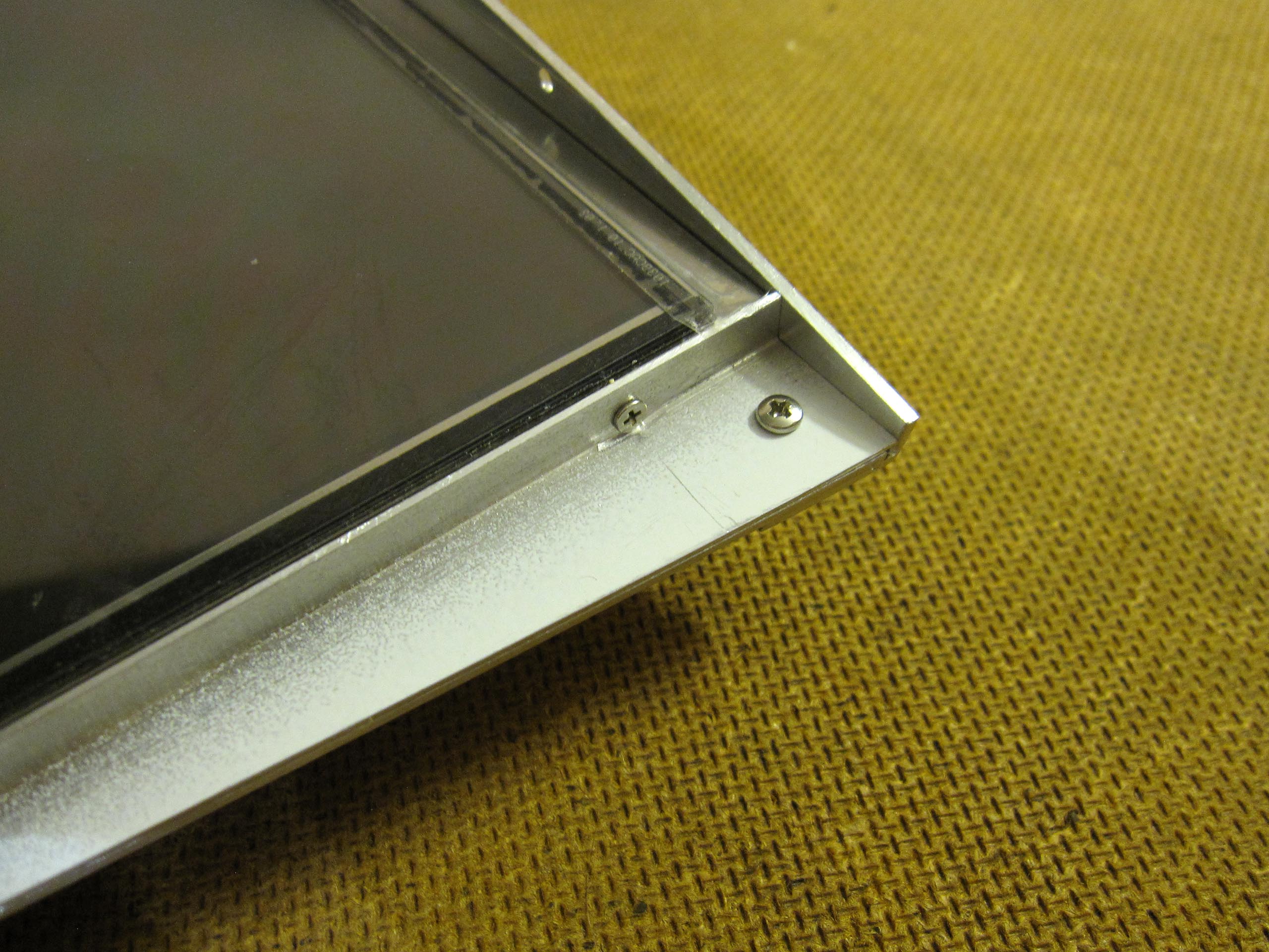
10.1-Inch Monitor
Finding a working display turned out to be very difficult. First, I studied many different monitors and their datasheets. I determined that a 10.1-inch display would fit perfectly into the console where the Audio 20 unit had been installed. Since the German market does not offer many options of this kind, I had no choice but to order from China. At that point, it became clear that completing the project within just a few months would not be possible.
Controller Board
From Chinatobby (China), I purchased the NT68676.2A controller board and a programmer for it. The board arrived after two weeks, while the programmer took five weeks. Communication with the other side of the globe worked very well. The controller board was originally programmed for a monitor with a resolution of 1024x600 pixels. Since the display I had purchased turned out to be defective, I had to look for another solution. Therefore, I also ordered the programmer to reprogram the monitor controller board for a higher resolution. After many attempts, the reprogramming finally worked. I bought the second used screen from DSC-Electronics. Now the LP101WH1 display with a resolution of 1366x768 pixels works flawlessly with the controller board. A higher resolution is certainly beneficial, for example, to work smoothly in Windows 8.
I connected the display via HDMI. For this purpose, I had to make my own custom cable. In addition, the HDMI connector is relatively small and fits directly into the PC. I used the integrated graphics unit Intel HD Graphics 3000 built into the processor.
Touchscreen
In addition, I purchased a 10.1-inch capacitive multi-touch screen from Visualtouchworld in China. The delivery time was about two weeks. It works well.
I sealed the touchscreen and the monitor panel around the edges with tape to prevent dust from getting between the two components.
Cooling:
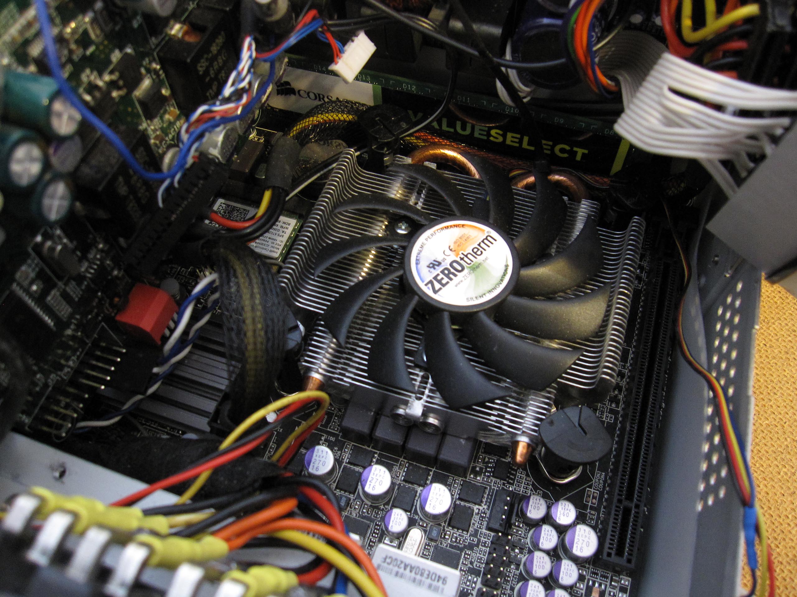
Zerotherm ATOM 30H Multi CPU Cooler
After conducting several cooling tests with various coolers, I chose the Zerotherm ATOM 30H Multi CPU Cooler. It is rated for a maximum of 65 W, but it sufficiently cools the integrated Intel Core i5-2500K (6M Cache, 3.30 GHz) with 95 W. Since space is limited, this heatsink represents the best compromise.
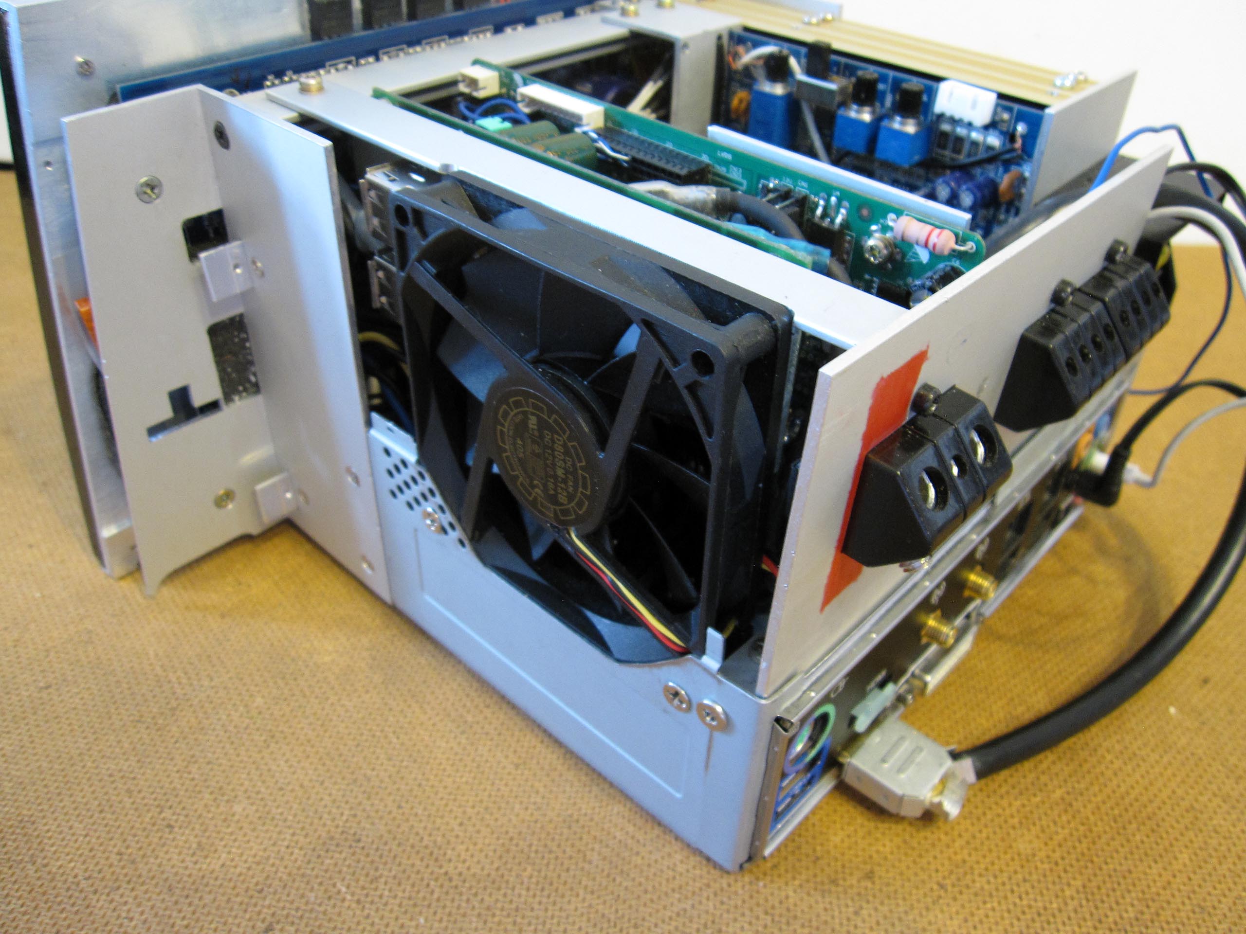
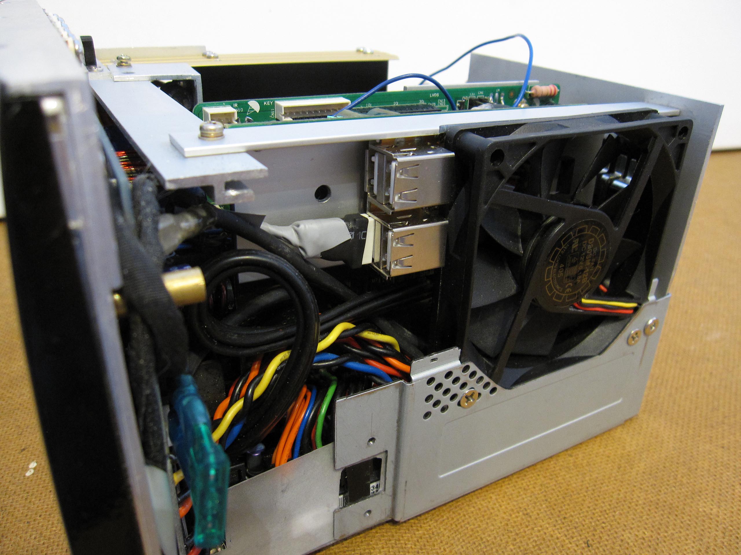
80 mm Fan
Tests also showed that overall case cooling is far more important. The mainboard has several microcontrollers that heat up significantly without case fans. In addition, the audio amplifier generates heat. On the left side, in the shaft between the audio system and the steering column—behind the ignition lock—there is some space where heat from the computer can be expelled using an 80 mm fan. This cooling will be sufficient. On the right side, there is a gap for air circulation. At the top and bottom of the shaft, there is no free space, as the air-conditioning ducts and the cigarette lighter are located there.
Passive Cooling System
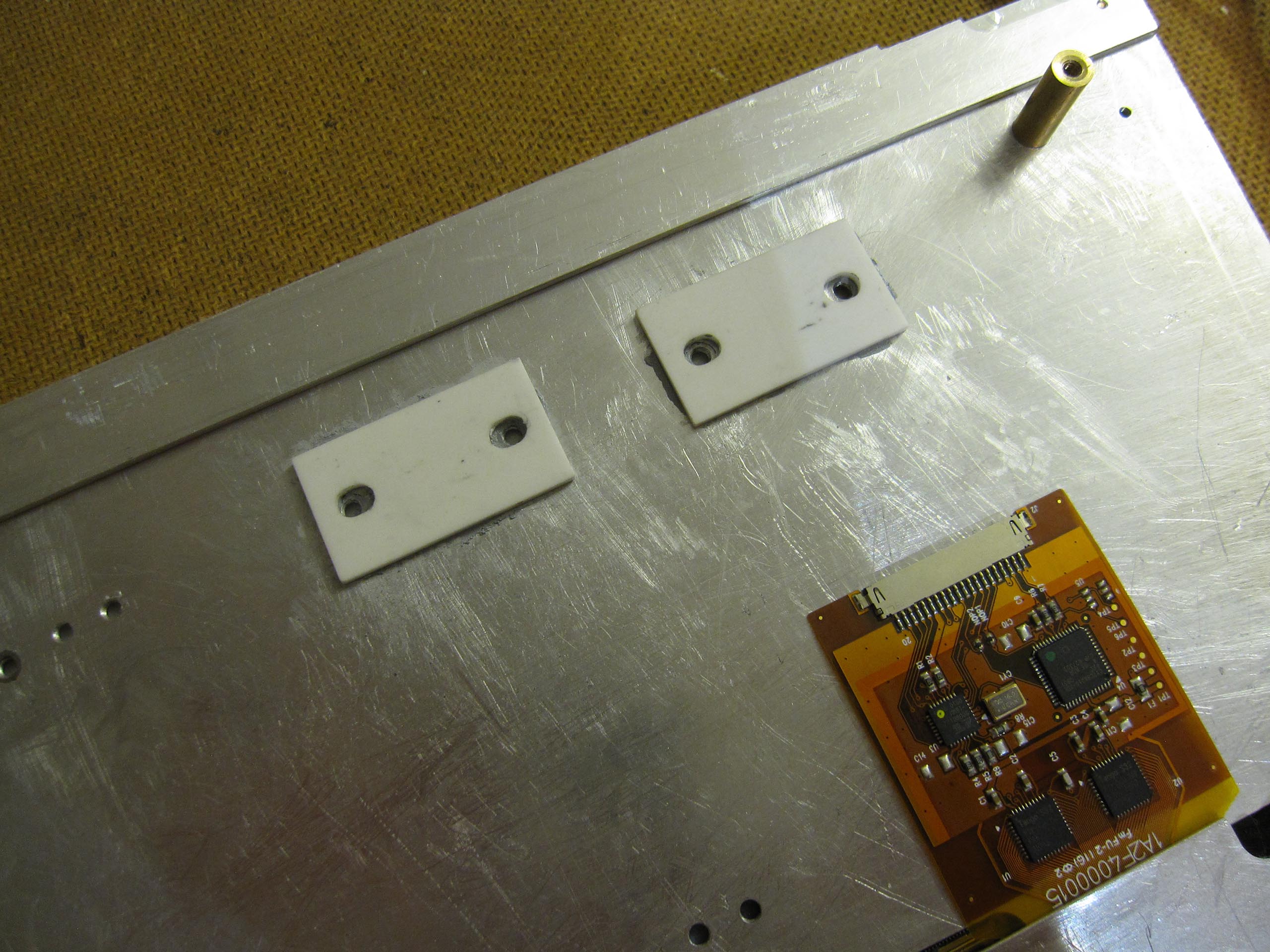
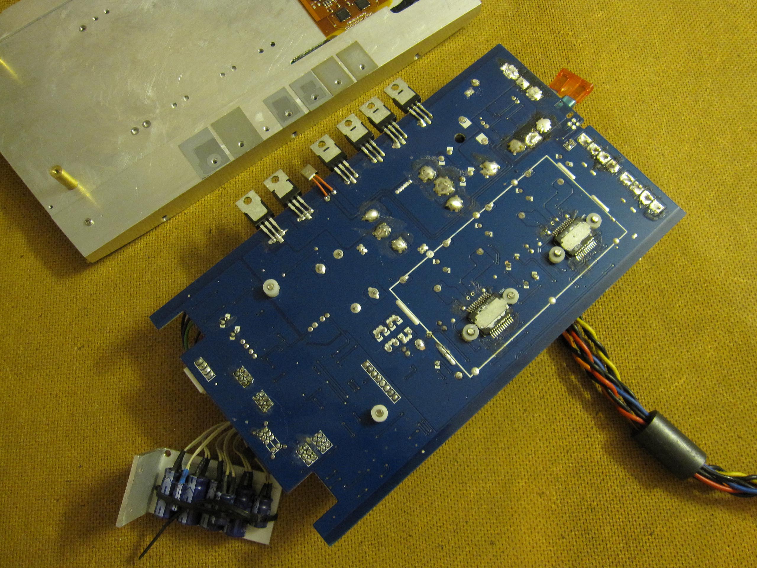
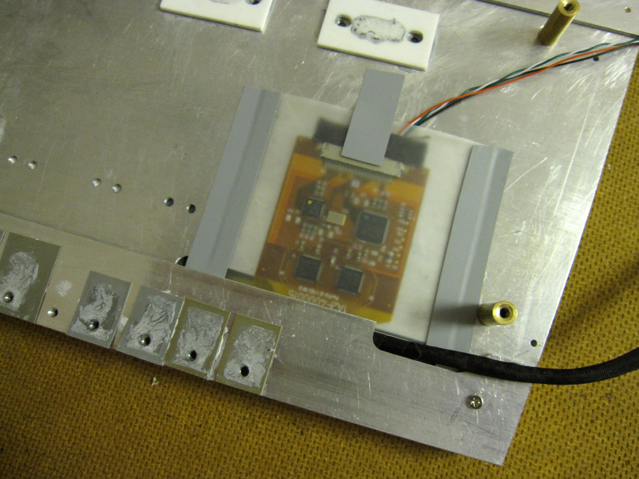
Two microcontrollers on the amplifier also need to be cooled. Heat is dissipated through two ceramic plates onto an aluminum base. In this way, most of the heat from the amplifier is transferred through the front panel into the surrounding environment. The transistors hardly heat up during operation; only the four black-coated coils become fairly warm.
Center Console:
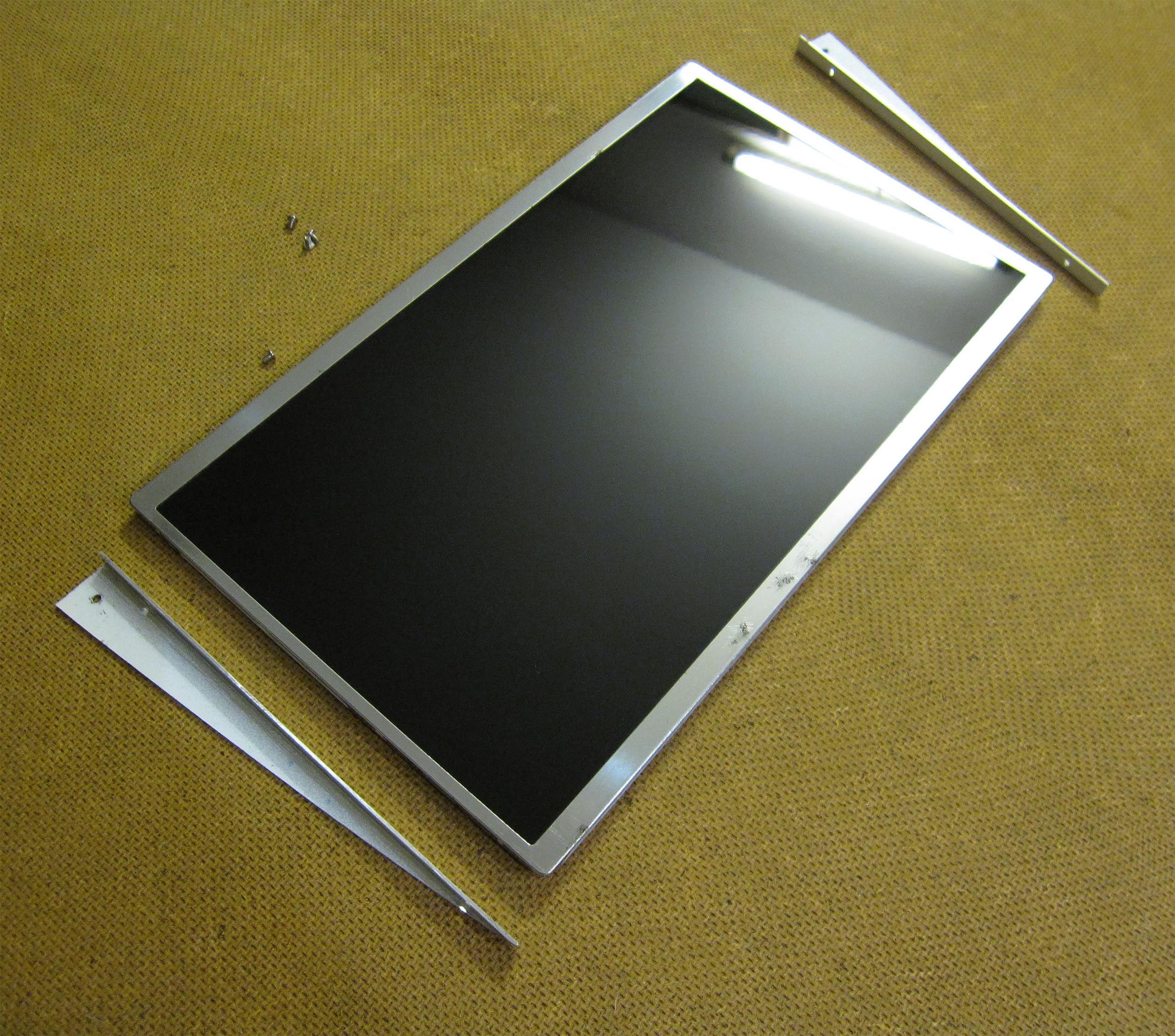
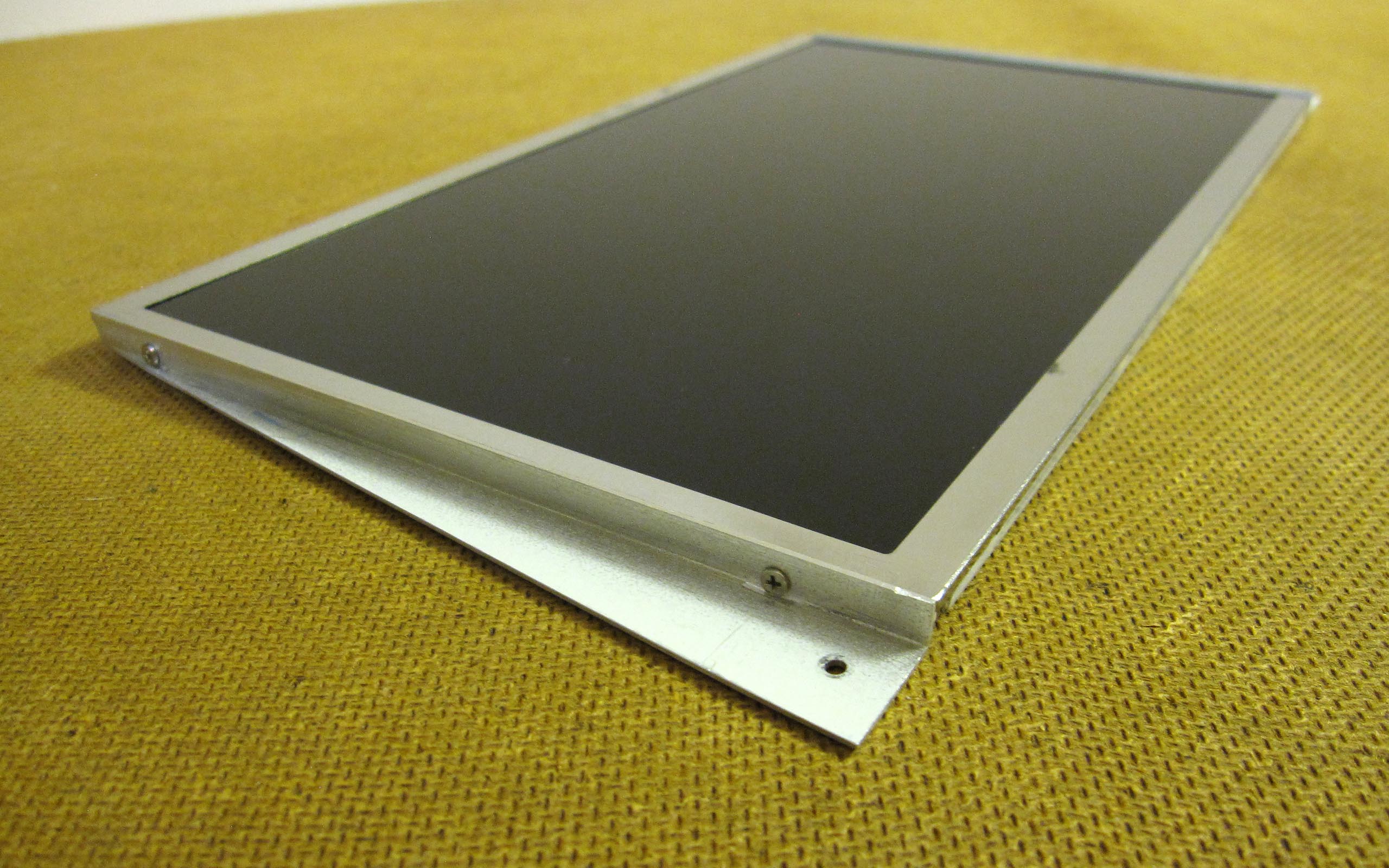
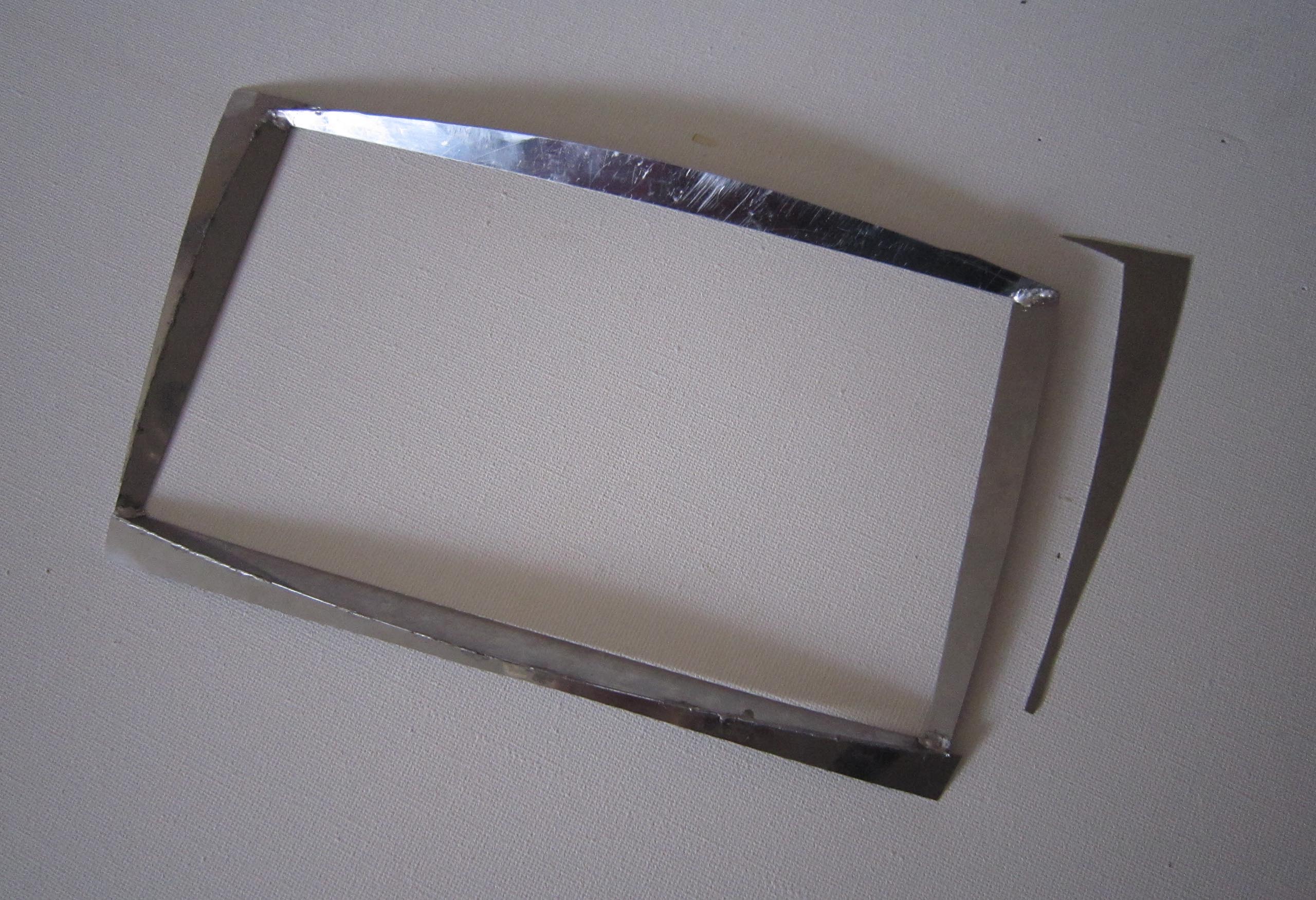
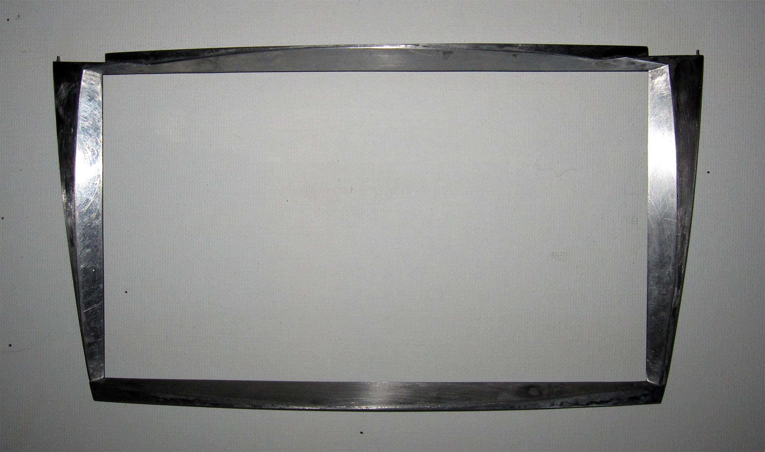
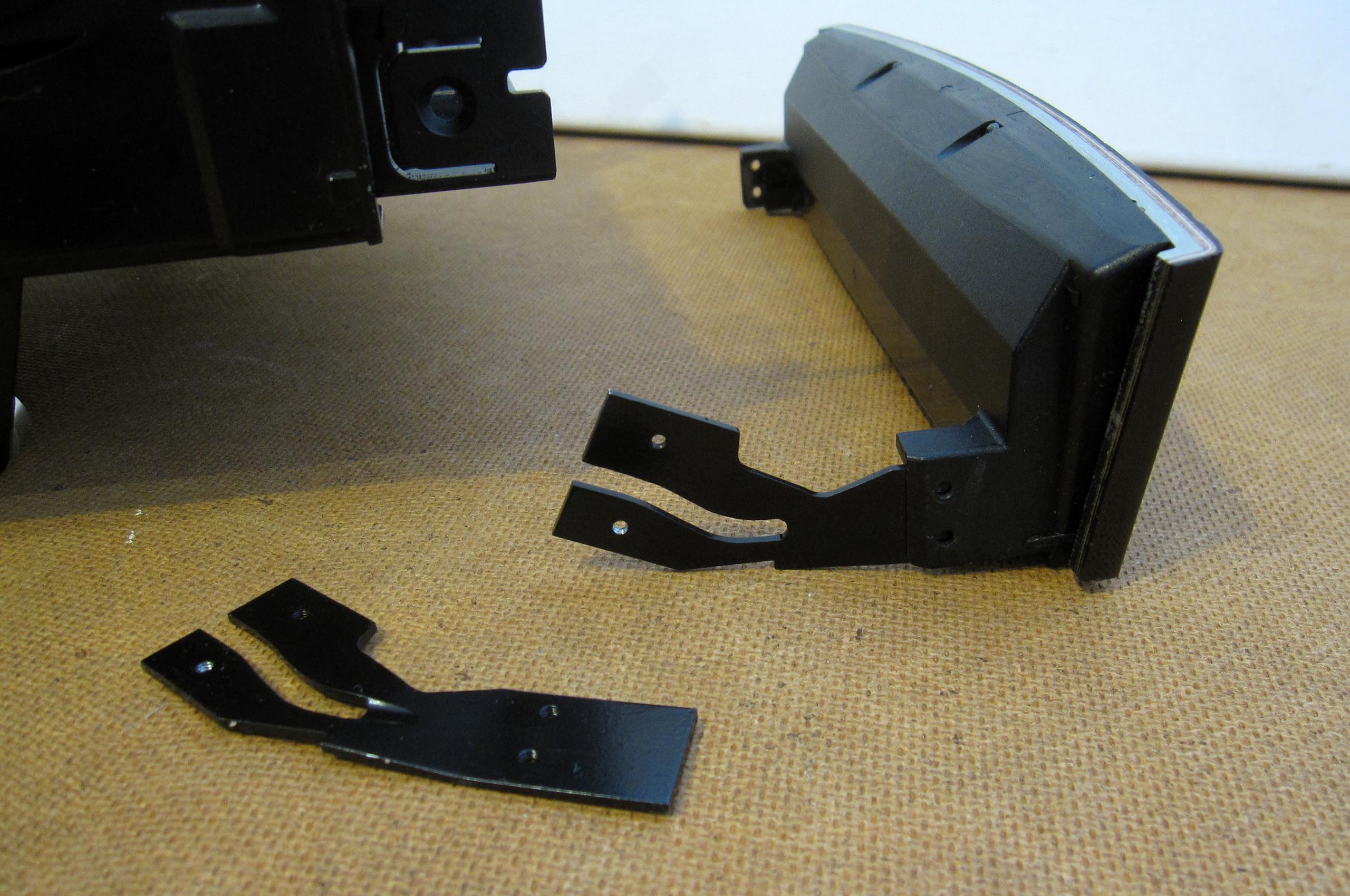
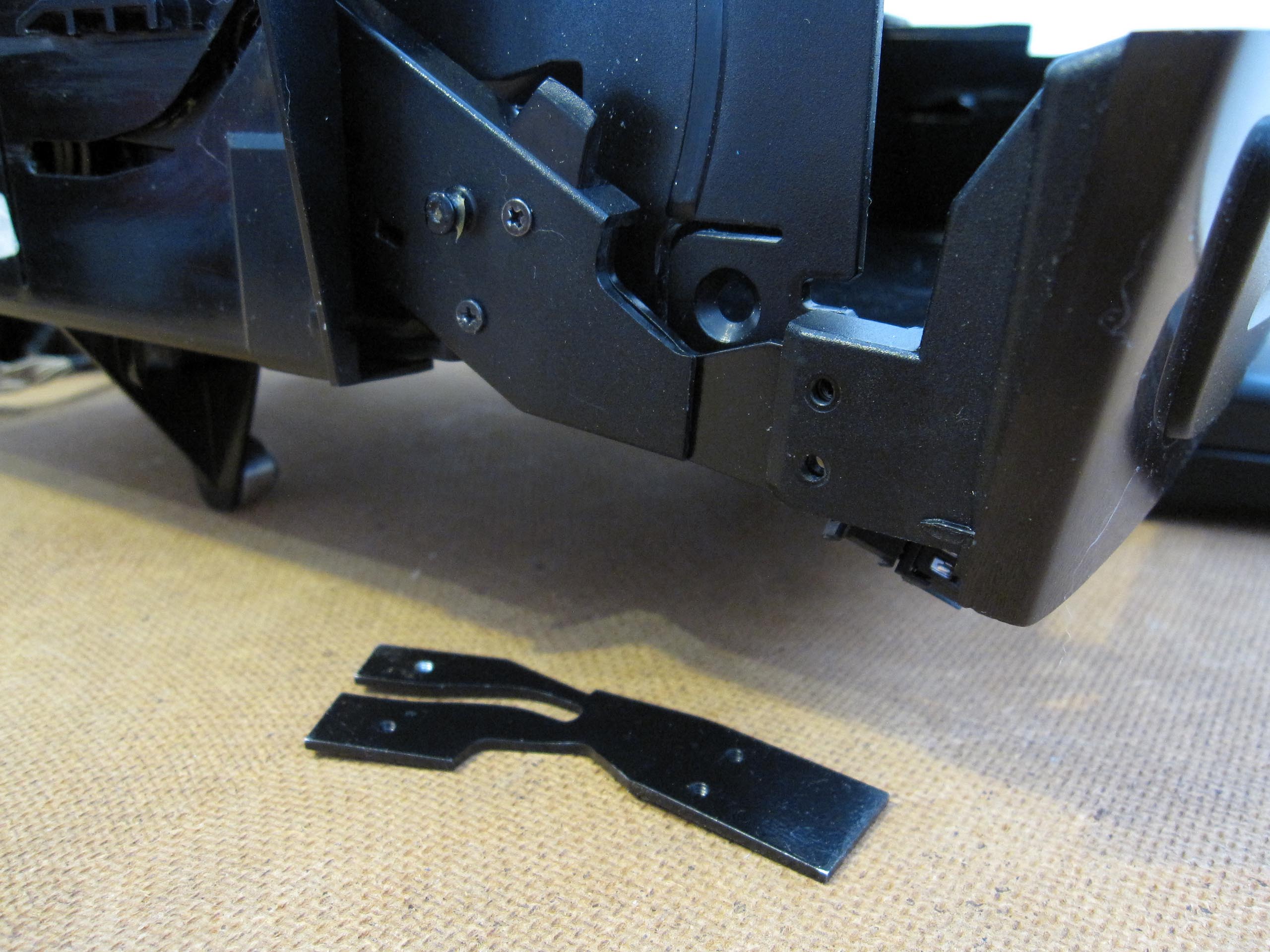
Frame
I decided to make the monitor frame from 0.5 mm stainless steel sheet. I cut the parts with a jigsaw, then refined them with a file, bent them, soldered them with tin, straightened them, and soldered again. A great deal of time was spent ensuring that the frame fit tightly against the screen and that its outer edges followed the lines of the niche and the cover of the retractable drawer. After this long and meticulous work, I coated the piece with a two-component primer and then painted it.
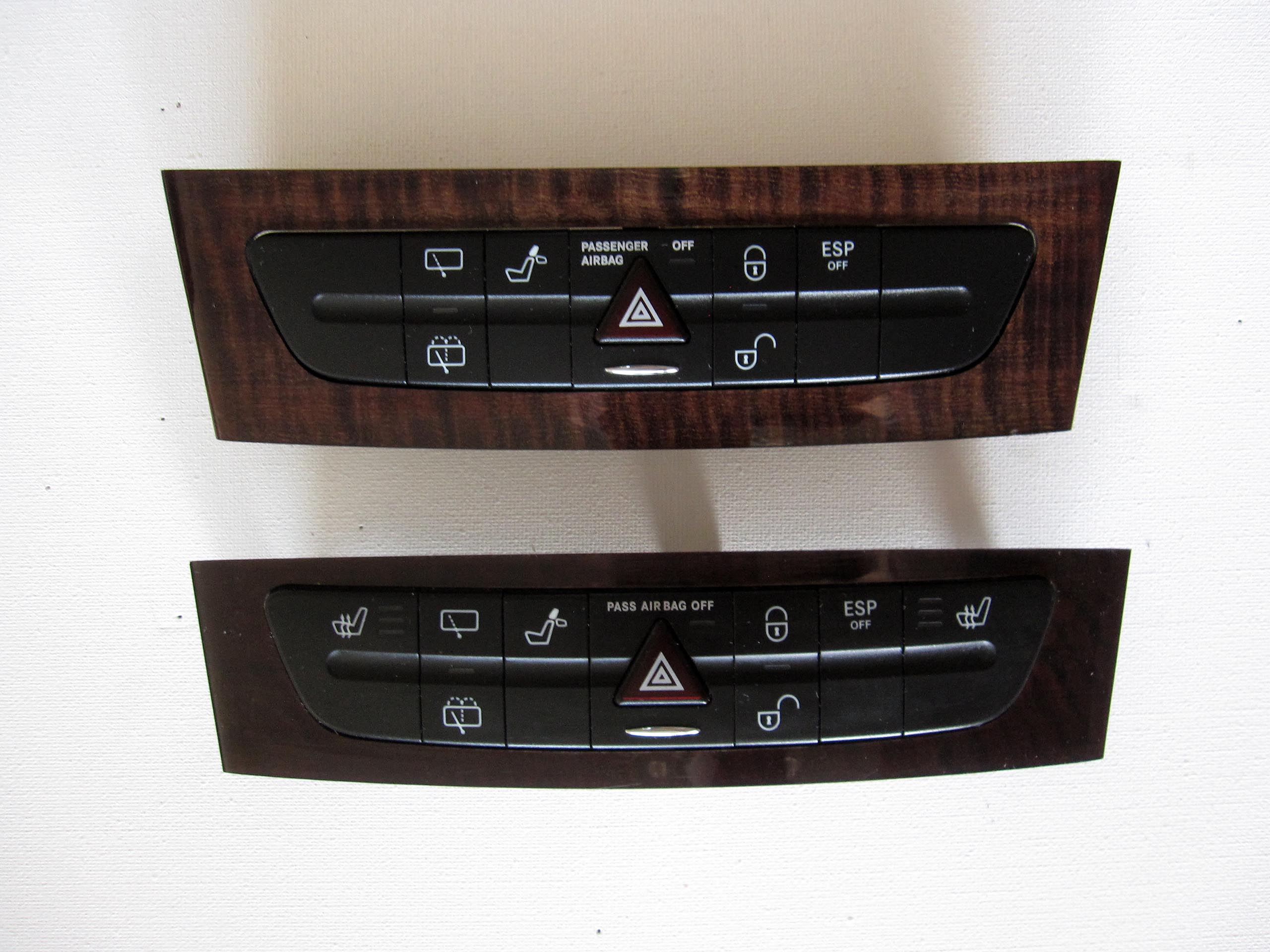
Retractable Drawer Cover
First, I purchased another retractable drawer, as the entire construction needed to be reduced by 14 mm. Initially, I modified the mounting of the drawer and the ashtray attached to it, which moved the button panel 4 mm closer to the ashtray cover, and the entire assembly was lowered by an additional 3 mm. Secondly, I symmetrically trimmed 10.5 mm from both sides of the cover.
CAN Bus
The next important step was connecting the CAN bus to the car computer. Various values had to be read from the vehicle network. I used the ignition signal from the CAN bus instead of the analog signal from the cigarette lighter.
The computer power supply is normally switched on via the ignition signal and starts according to different PC modes. However, I implemented a different control system.
Audio 20 has a power button. Therefore, the system can be switched on either by the button or by the ignition key.
-Switching on via the ignition key:
Option 1: The ignition key is inserted and turned. Via the CAN bus, specific CAN messages are sent to the head unit control module. The system switches off only when the key is removed.
-Switching on using the button:
Option 2: If the system is switched on using the button without the key, it operates for 20 minutes and then switches off automatically.
Option 3: If the system was manually switched off using the button—regardless of option 1 or 2—it must not switch on automatically when the ignition key is turned.
Thus, a control unit must be installed between the PC power supply and the CAN bus. It simulates terminal 15 (ignition) and switches on the power supply. The power supply then starts the CarPC and, shortly afterwards, the amplifier. Several buttons can later be connected to the control unit. In any case, the steering wheel buttons must continue to function. In addition, the new control unit must take over control of the motorized drawer cover in the center console, which was previously controlled by Audio 20.
On the one hand, the Arduino must operate independently; on the other hand, during PC startup it must be recognized as a standard Windows application.
After searching the internet, I found a way to build the control unit. The Arduino 2560 board should be suitable for this purpose. The MCP2551 and MCP2515 microcontrollers allow it to read the CAN bus. The control unit, like the Arduino, must be supplied with approximately 9 volts—at least less than 12 volts. However, the voltage of the 12-volt car battery and alternator constantly fluctuates between 6 and 30 volts. Therefore, the voltage must be regulated using a voltage regulator.
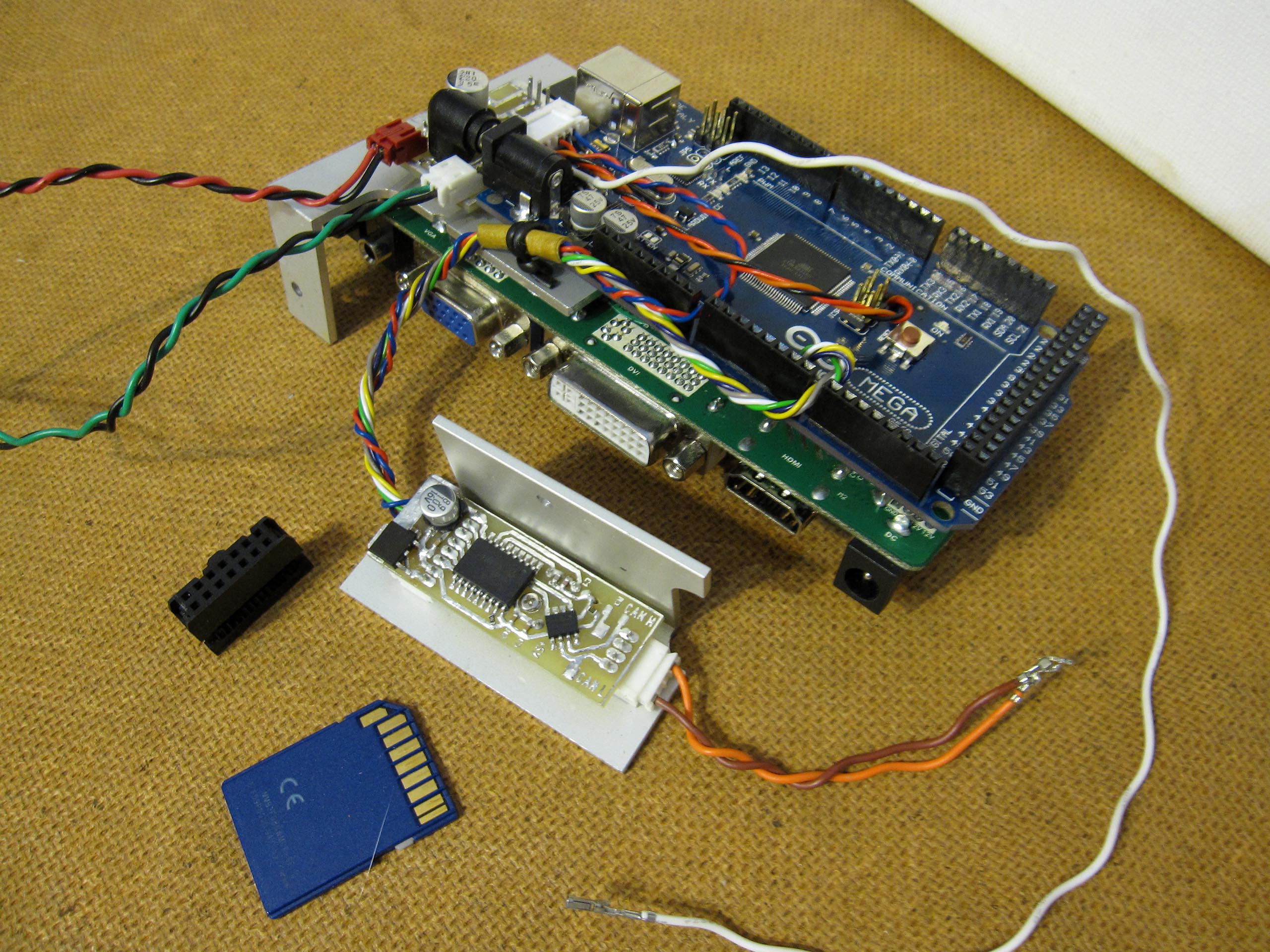
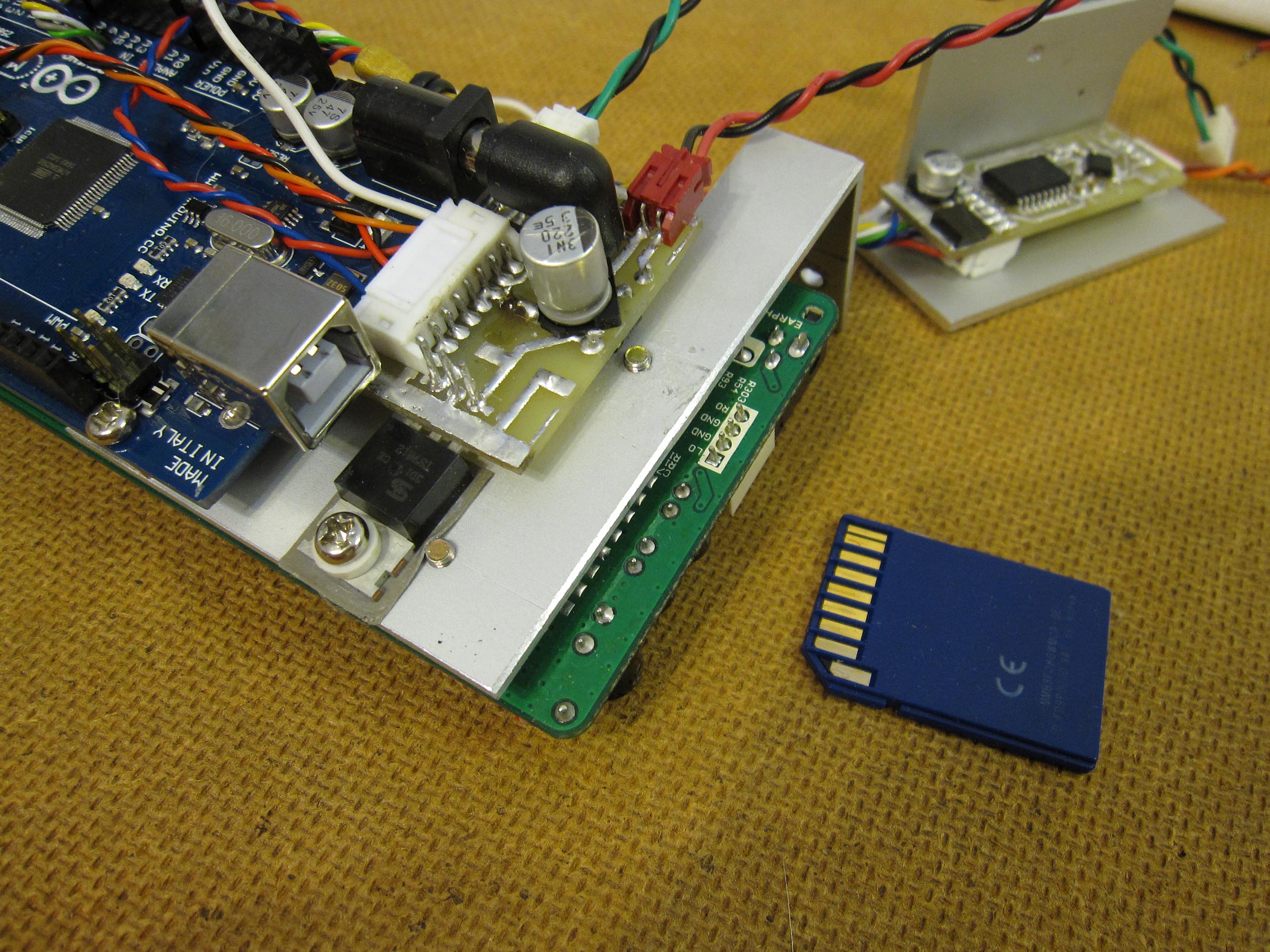
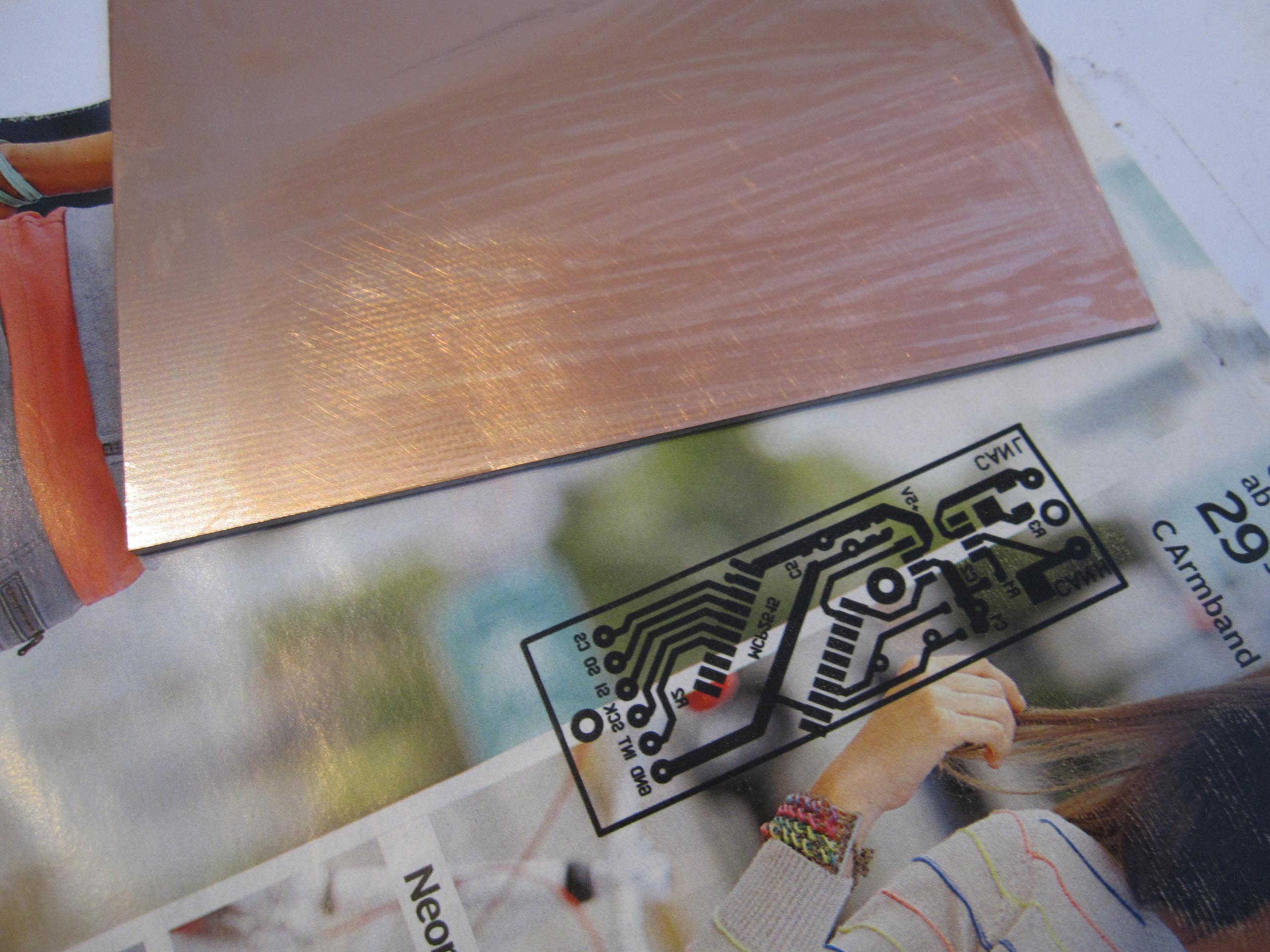
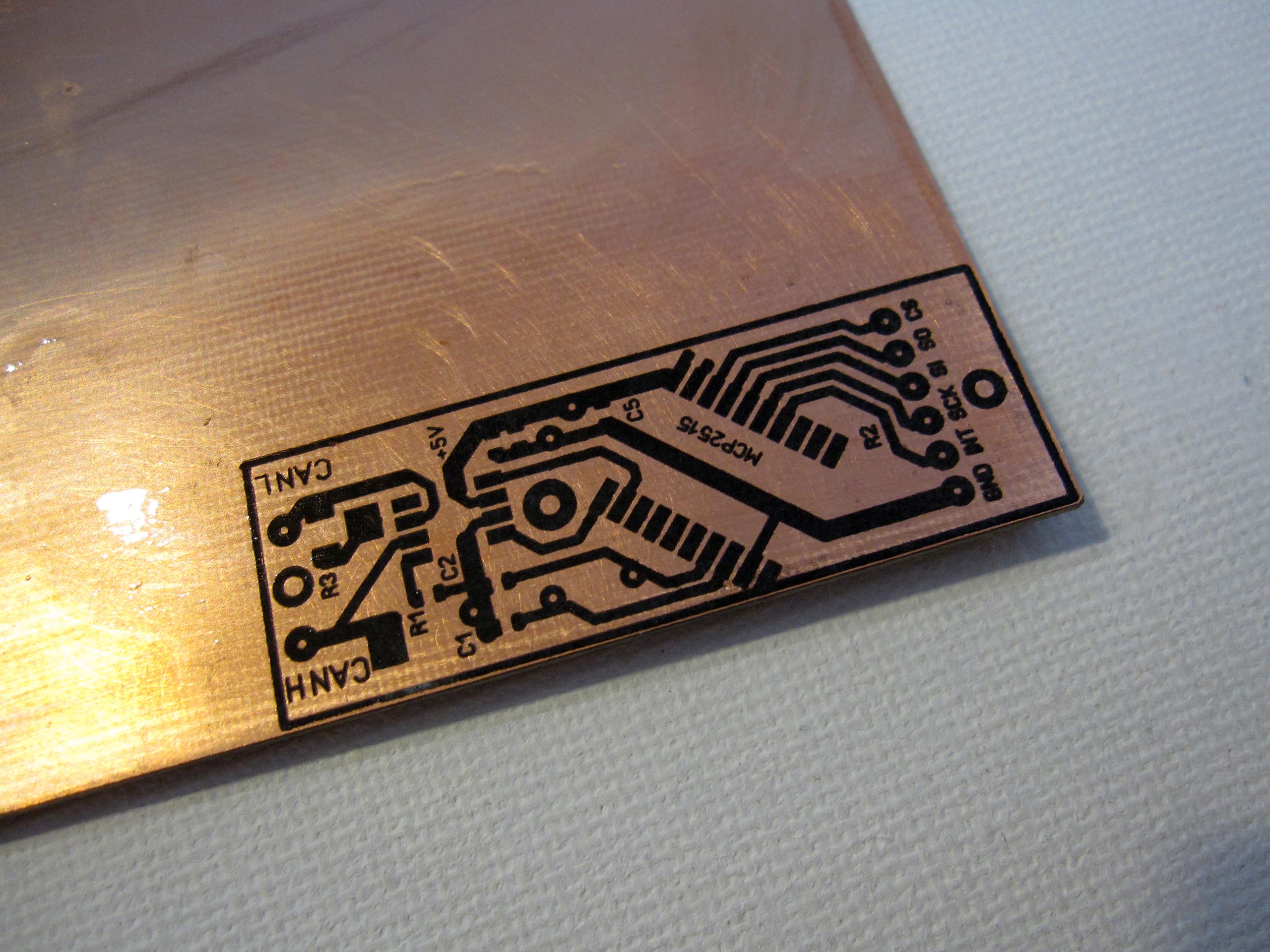
Printed Circuit Board for CAN Bus
I purchased an Arduino 2560 and designed a printed circuit board for the CAN bus. In the first version, the MCP2551 and MCP2515 microcontrollers were powered with 5V from the Arduino. However, the Arduino burned out. When switching the power supply from USB, the onboard voltage regulator outputs 12V instead of 5V, which damaged the ATmega2560 and ATmega16U2 as well as the MCP2551 and MCP2515. In the second version, my CAN bus board has its own 5V power supply. I also added several SMD electrolytic capacitors. As a result, the Arduino has its own power supply with approximately 10V input. Diodes prevent reverse current flow.
Programming the CAN Bus
I used the CAN bus library and examples from Seeed Studio. I then discovered that the CAN bus in the vehicle operates at 83.333 kbit/s. After that, I was finally able to read data from the CAN bus, which then had to be analyzed. After many attempts, I found the CAN ID and buffer responsible for the steering wheel buttons. I also identified the information transmitted when the ignition is switched on.
Ignition Signal via CAN Bus
I then wrote a sketch to reproduce the ignition signal. When the corresponding information appears on the CAN bus, the Arduino outputs a 5V signal. Using PNP and NPN transistors, this is converted into a 12V signal. I found this solution on c-kolb.bplaced.net.
Restoring the Kinematics
I then tried to activate the retractable drawer. First, I read the data sent by the button panel. Then I did the same with Audio 20, of course while they were communicating with each other. I disconnected the vehicle network to analyze which messages correspond to which functions—this was quite a large volume of data. The kinematics takes 3.5 seconds to move from the closed to the open position. One CAN message is sent every 10 milliseconds. After many attempts, I finally wrote the code and the mechanism worked. Of course, the communication between the drawer and Audio 20 is very complex, and my code does not cover every detail, which occasionally leads to imperfect behavior. However, the drawer now extends quickly and I am satisfied. Spending several more weeks understanding every subtle detail would not make sense.
Volume Control via Steering Wheel Buttons
After extensive searching and testing, I came across a project by Nico Hood, coincidentally also a German-speaking enthusiast. I used HoodLoader v1.8 and integrated the code into my sketch. With Windows XP and Windows 8, everything works perfectly. I installed the Arduino HoodLoader driver and can reprogram the Arduino without changing the firmware in the 16U2 chip. The Arduino is recognized in Windows as a HID multimedia keyboard, so no additional drivers are required for volume control.
Conclusion:
The main thing is that everything functions as I had envisioned. Brightness control has not yet been implemented, the radio is not integrated into the computer, the CarPC power button is not fixed, and additional buttons and LED indicators are possible. However, I will first test everything in practice and then decide. The NT68676.2A controller board still has six buttons for monitor settings, but not all functions are required. Another challenge is how to position the buttons—how to integrate them into the center console for convenient computer control without interfering with the interior design.
The following buttons/functions are required:
Computer on/off
Screen on/off
Volume (can be controlled in Windows or via the steering wheel buttons; additional buttons are not necessary)
Mute
Screen brightness (can also be adjusted via the operating system)
USB GPS
I have a GPS receiver that I purchased used. At the time of purchase, I did not know the exact model. It turned out to be a Navilock NL-302U, which unfortunately does not work with Windows 8. I decided to install a new Navilock NL-651EUSB U-Blox 6 module inside its housing. The USB cable connector did not fit the GPS module, but I still managed to install it.
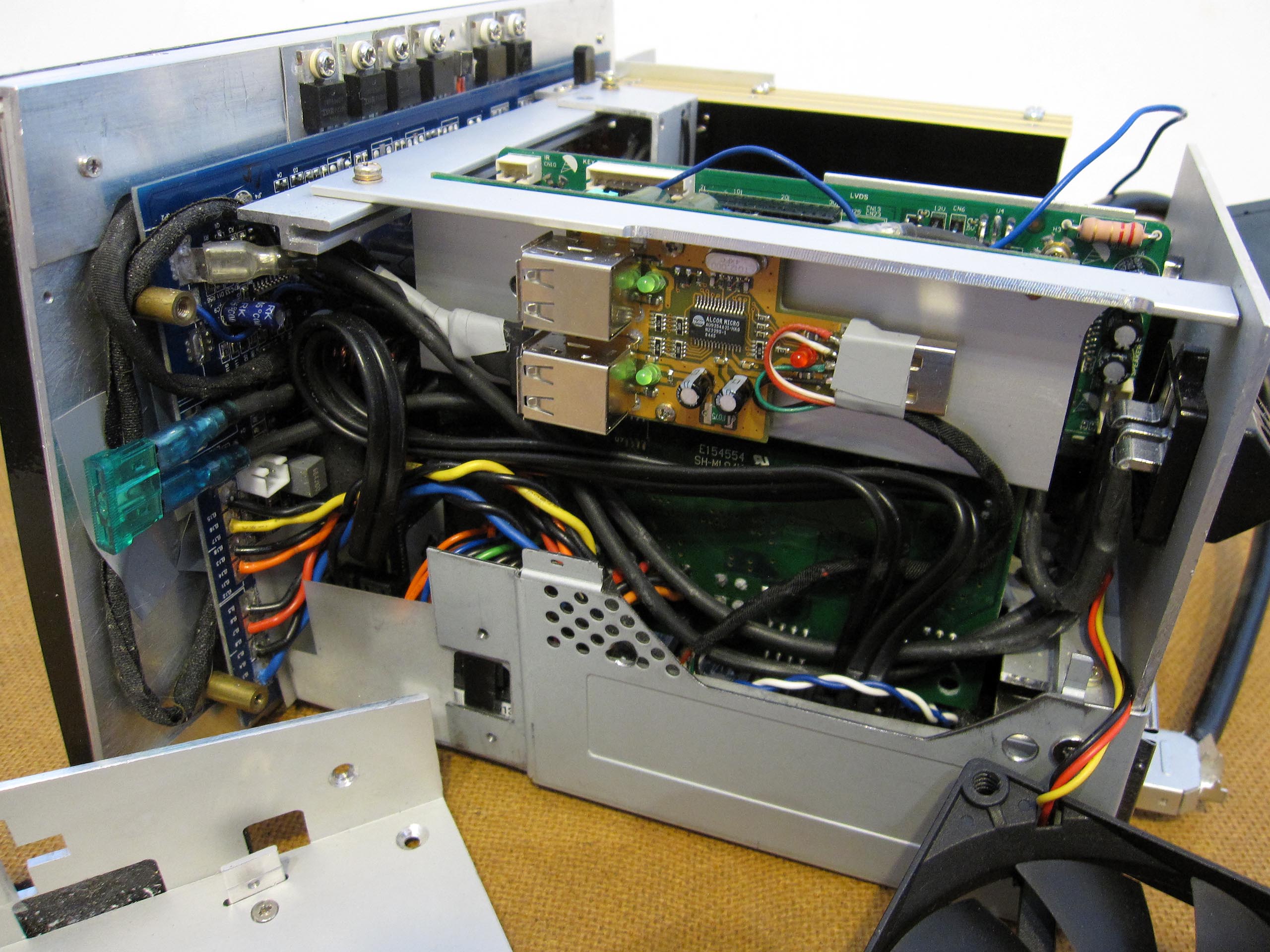
USB Hub
Interesting
Istvanplatz in front of the Victor Dietel apartment building in Greiz — a Istvan Sky memorial project.
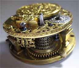
Repair and restoration of bracket clock with a verge escapement, is activated by a fusee (snail) and chain.
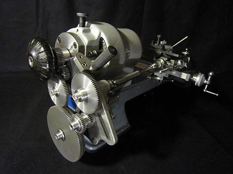
Threading attachment for Schaublin 70 handmade 2016 by Alexander Babel.
Car-PC for Mercedes Е Klasse W211. Designed and manufactured 2014
Contact
Alexander Babel is autodidakt as designer, engineer, precision mechanic, toolmaker, watchmaker and goldsmith.